Channelized log-periodic antenna with matched coupling

a log-period antenna and coupling technology, applied in the field of antennas, to achieve the effect of efficient couplement and increase forward gain

Active Publication Date: 2006-11-23
RGT UNIV OF CALIFORNIA
View PDF12 Cites 22 Cited by
  • Summary
  • Abstract
  • Description
  • Claims
  • Application Information

AI Technical Summary

Benefits of technology

[0017] 4) In addition, a lens can be used with the channelized planar LP antenna to increase forward gain. A typical LP antenna has a main beam f-number (f/#) of approximately 0.7. The use of a silicon elliptical lens slows the feed

Problems solved by technology

Many wideband planar antennas are described in the literature, but one challenge is to produce an antenna that is capable of measuring two pola

Method used


Image

  • Channelized log-periodic antenna with matched coupling
  • Channelized log-periodic antenna with matched coupling
  • Channelized log-periodic antenna with matched coupling

Examples


Embodiment Construction

[0029] The present invention relates to systems, methods, materials and structures linking a log-periodic (LP) antenna to a log-periodic channelizer through a taperline balun to produce an integrated device suitable, for example, as a broadband telescope feed. The photometric channels included in some embodiments of this device would typically have substantially identical coupling to a radio telescope aperture.

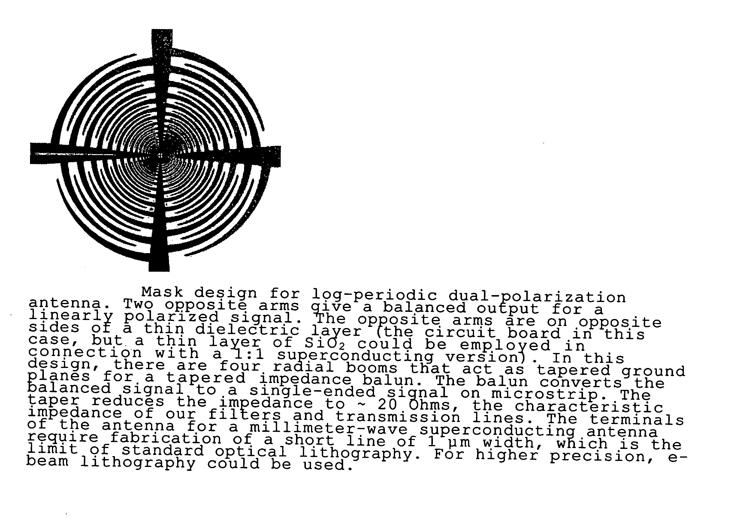
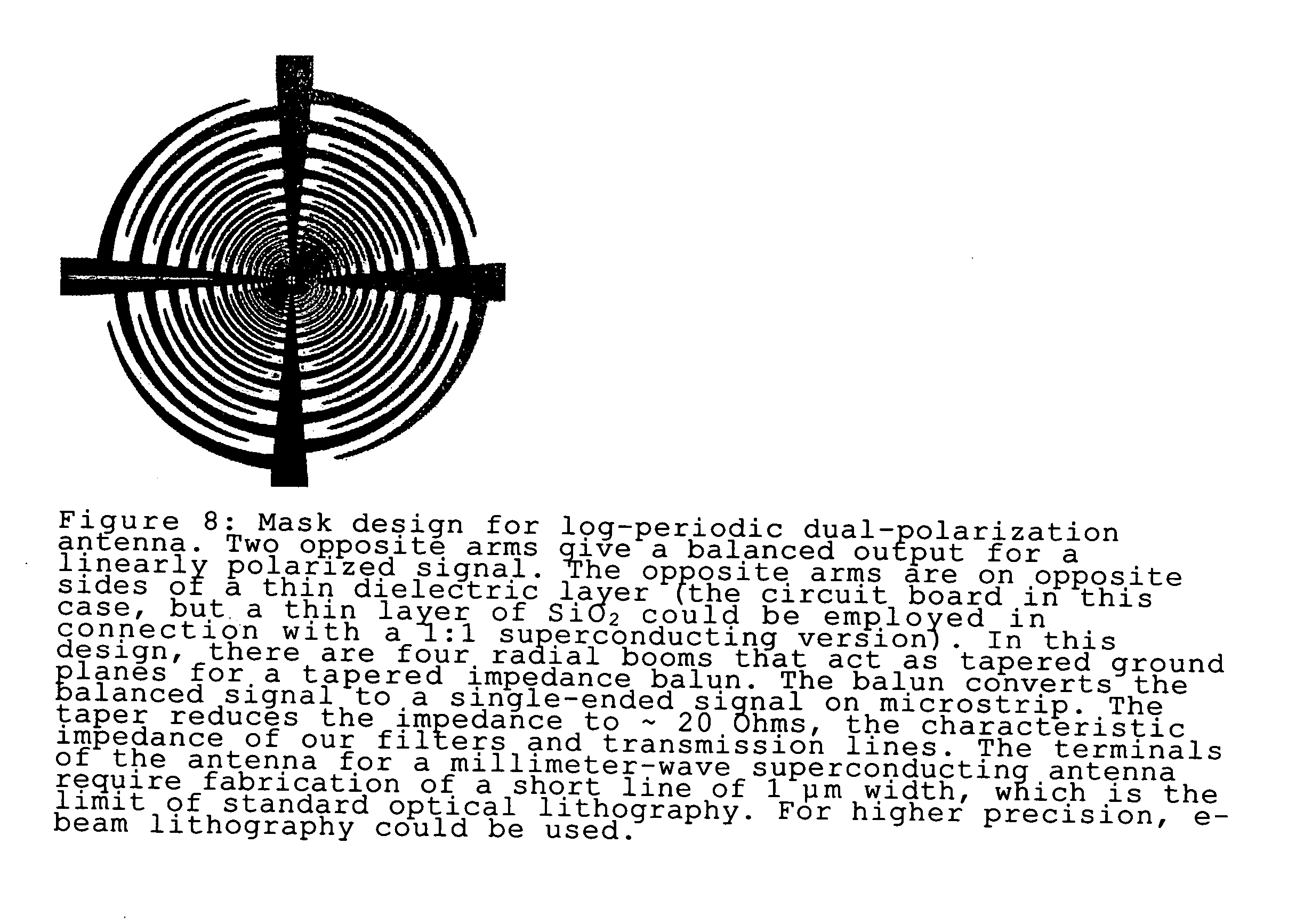
[0030] A typical log-periodic antenna is an array of switched dipoles of similarly shaped conductors, where adjacent conductors differ in size by a constant scale factor τa and the bandwidth of the antenna is determined by the largest and smallest dipole of this array. The antenna characteristics vary periodically with the logarithm of the frequency with a period of log(τa).

[0031] A log-periodic channelizer is effectively a multi-port circuit that includes a broadband input and a series of simple diplexers and channel-defining filters of substantially equal electrical length...


PUM


Abstract

A log-periodic antenna coupled to a channelizer is described in which matched scale constants for the antenna and the channelizer are used to achieve substantially identical coupling over each fractional bandwidth channel. Embodiments for simultaneous dual polarization operation are described as well as embodiments suited for planar lithographic fabrication.

Description

CROSS REFERENCE TO RELATED APPLICATIONS [0001] This application claims priority pursuant to 35 USC § 119 from provisional patent application Ser. No. 60 / 679,264 filed May 9, 2005 the entire contents of which is incorporated herein by reference for all purposes.STATEMENT REGARDING FEDERALLY SPONSORED RESEARCH OR DEVELOPMENT [0002] This invention was made with Government support under Grant (Contract) No. AST-0096933 awarded by the National Science Foundation. The Government has certain rights to this invention.BACKGROUND OF THE INVENTION [0003] 1. Field of Invention [0004] The present invention relates to the field of antennas and, more particularly, to channelized log-periodic antennas. [0005] Financial support from the SETI Institute, made possible by the Paul G. Allen Foundation, is gratefully acknowledged. [0006] 2. Description of the Prior Art [0007] Astronomical observations in spectral regions ranging from approximately the far infrared (far IR) wavelengths to millimeter (mm) ...

Claims


Application Information

Patent Timeline
IPC IPC(8): H01Q11/10
CPCH01Q1/10H01Q19/062H01Q9/27H01Q1/38
Inventor ENGARGIOLA, GREGORYLEE, ADRIAN
Owner RGT UNIV OF CALIFORNIA
Why Eureka
Try Eureka