
Multi-arc microstrip dielectric resonant cavity antenna based on 3D printing technology

A dielectric resonant cavity and 3D printing technology, applied in the directions of resonant antennas, antennas, slot antennas, etc., can solve the problems of low efficiency and large ohmic loss

Active Publication Date: 2020-09-25
NANJING UNIV OF INFORMATION SCI & TECH
View PDF6 Cites 0 Cited by
  • Summary
  • Abstract
  • Description
  • Claims
  • Application Information

AI Technical Summary

Problems solved by technology

[0003]Aiming at the above problems, the present invention proposes a multi-arc microstrip dielectric resonator antenna based on 3D printing technology to solve the ohmic problem of ordinary metal antennas in the high frequency band. The problem of too much loss and too low efficiency is suitable for 5G millimeter wave band

Method used


Image

  • Multi-arc microstrip dielectric resonant cavity antenna based on 3D printing technology
  • Multi-arc microstrip dielectric resonant cavity antenna based on 3D printing technology
  • Multi-arc microstrip dielectric resonant cavity antenna based on 3D printing technology

Examples


Embodiment Construction

[0015] In order to make the purpose, technical solution and advantages of the present application clearer, the present application will be further described in detail below in conjunction with the accompanying drawings and embodiments. It should be understood that the specific embodiments described here are only used to explain the present application, and are not intended to limit the present application.

[0016] Reference herein to an "embodiment" means that a particular feature, structure, or characteristic described in connection with the embodiment can be included in at least one embodiment of the present application. The occurrences of this phrase in various places in the specification are not necessarily all referring to the same embodiment, nor are separate or alternative embodiments mutually exclusive of other embodiments. It is understood explicitly and implicitly by those skilled in the art that the embodiments described herein can be combined with other embodiment...


PUM


Abstract

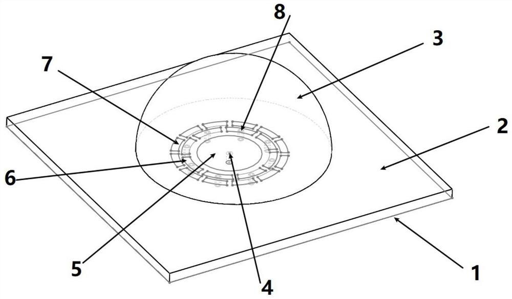
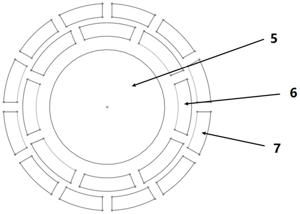
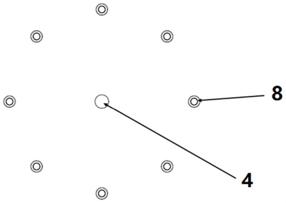
The invention discloses a multi-arc microstrip dielectric resonant cavity antenna based on a 3D printing technology. A main radiation unit is a hemispheroid medium, and compared with a metal material,the ohmic loss is lower, and the efficiency is higher. Because photosensitive resin is used as a medium, the shape can be changed as required. The radius is slightly greater than one wavelength, andthe antenna is coupled with the current of the feed sheet, so that the radiation direction can be guided, the gain reduction caused by the dispersion of electromagnetic waves to the periphery is avoided, and the bandwidth is improved. The two layers of multi-arc micro-strips block diffusion of current to the periphery to a certain extent, and play a certain role in restraining a magnetic field, sothat backward gain is reduced, forward gain is improved, and bandwidth is further improved. And the metallized via holes are adopted, and the ground plate and the arc microstrip are connected, and therefore, current diffusion can be further suppressed, and the gain of the antenna can be improved to a certain extent.

Description

technical field [0001] The invention relates to the technical field of antennas, in particular to a multi-arc microstrip dielectric cavity antenna based on 3D printing technology. Background technique [0002] With the development of communication technology, it is difficult to obtain a wide continuous bandwidth in the communication frequency band below 6GHz. Because of the large amount of unused resources, millimeter wave has become a hot spot in 5g communication research. Research on communication antennas in wave frequency band. Due to the skin effect of the metal, the traditional microstrip antenna has high metal ohmic loss and low gain in the high frequency band, which limits its development and application. Contents of the invention [0003] In view of the above problems, the present invention proposes a multi-arc microstrip dielectric resonant cavity antenna based on 3D printing technology to solve the problem of too much ohmic loss and too low efficiency of ordina...

Claims


Application Information

Patent Timeline
IPC IPC(8): H01Q9/04H01Q13/10H01Q13/18H01Q1/38H01Q1/48H01Q1/50
CPCH01Q9/0485H01Q13/106H01Q13/18H01Q1/38H01Q1/48H01Q1/50
Inventor 于兵苏鹏邓健贾洪川刘沁沁鞠刘娟
Owner NANJING UNIV OF INFORMATION SCI & TECH
Learn More