High speed, high quality liquid pattern deposition apparatus

a liquid pattern deposition and high-speed technology, applied in the field of continuous stream type drop emitters, can solve the problems of limited drop-on-demand drop emitter systems, limited usefulness of drop-on-demand emitters for high, and low quality deposition of materials, so as to achieve high layer deposition process speeds and maintain drop volume uniformity

Inactive Publication Date: 2006-11-23
EASTMAN KODAK CO
View PDF7 Cites 12 Cited by
  • Summary
  • Abstract
  • Description
  • Claims
  • Application Information

AI Technical Summary

Benefits of technology

[0014] It is also an object of the present inventions to provide a liquid pattern deposition apparatus utilizing thermally stimulated continuous drop emitter that operates at high drop repetition frequencies enabli...

Problems solved by technology

Drop-on-demand drop emitter systems are limited in the drop repetition frequency that is sustainable from an individual nozzle.
However, a drop frequency maximum of 50 KHz limits the usefulness of drop-on-demand emitters for high quality patterned layer deposition to process speeds below ˜0.5 m/sec.
In light of these characteristics, it is surprising that CIJ drop generators have not been employed in high density arrays for very high speed, very high quality deposition of materials.
However, despite the need for apparatus to effect such deposition, for example apparatus to deposit high resolution patterns of electronic materials, no high density arrays have been reported or commercialized.
However, large arrays of CIJ jets having jets spaced more closely than 300 jets per inch, meeting the requirements desired for high quality patterned deposition of materials, have been difficult to fabricate using conventional nozzle fabrication methods such as nickel electroforming and drop generator assembly of multiple layers and piece parts.
It is quite difficult to produce uniform acoustic stimulation for long arrays of closely spaced jets.
Further, conventional CIJ nozzle fabrication methods have not been successful producing long arrays of nozzles having diameters less than 15 microns, as is needed to form drops of less than 10 pL.
Because of the difficulties of traditional CIJ fabrication techniques and acoustic stimulation, eve...

Method used


Image

  • High speed, high quality liquid pattern deposition apparatus
  • High speed, high quality liquid pattern deposition apparatus
  • High speed, high quality liquid pattern deposition apparatus

Examples


Embodiment Construction

[0047] The invention has been described in detail with particular reference to certain preferred embodiments thereof, but it will be understood that variations and modifications can be effected within the spirit and scope of the invention. The present description will be directed in particular to elements forming part of, or cooperating more directly with, apparatus in accordance with the present invention. Functional elements and features have been given the same numerical labels in the figures if they are the same element or perform the same function for purposes of understanding the present inventions. It is to be understood that elements not specifically shown or described may take various forms well known to those skilled in the art.

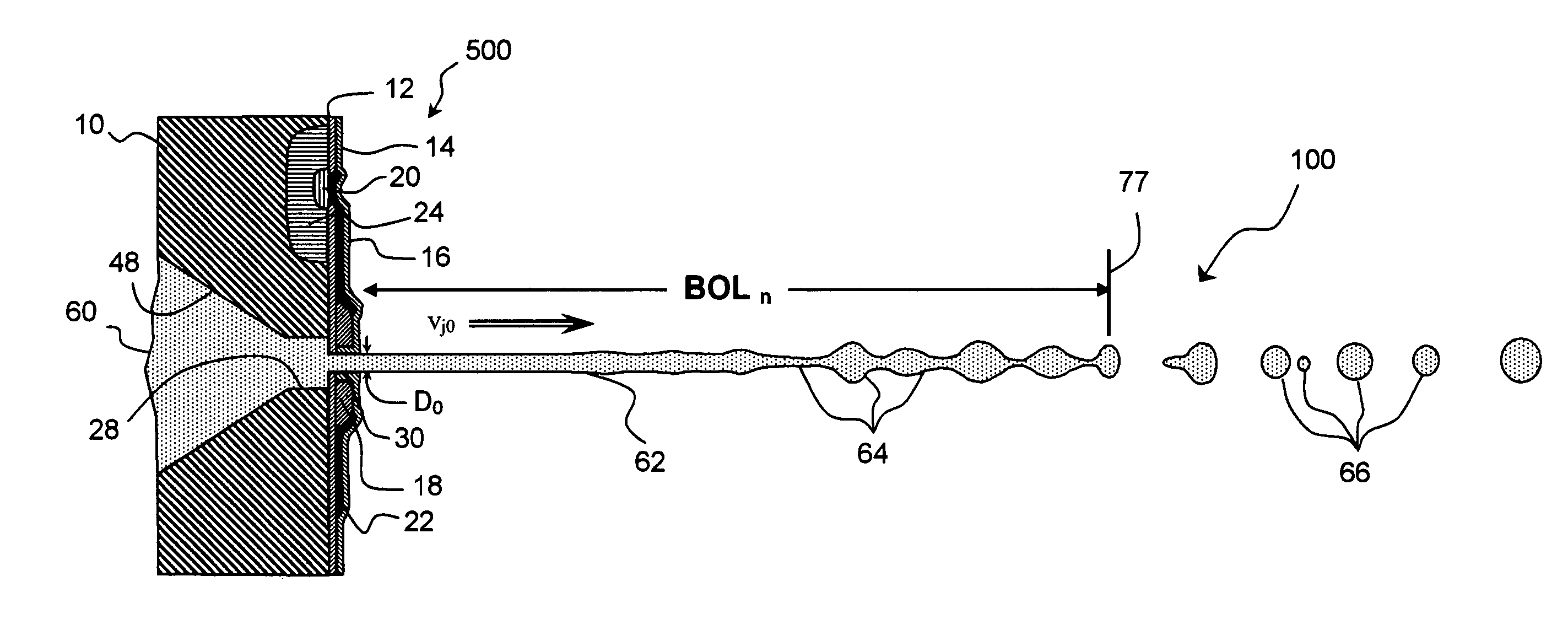
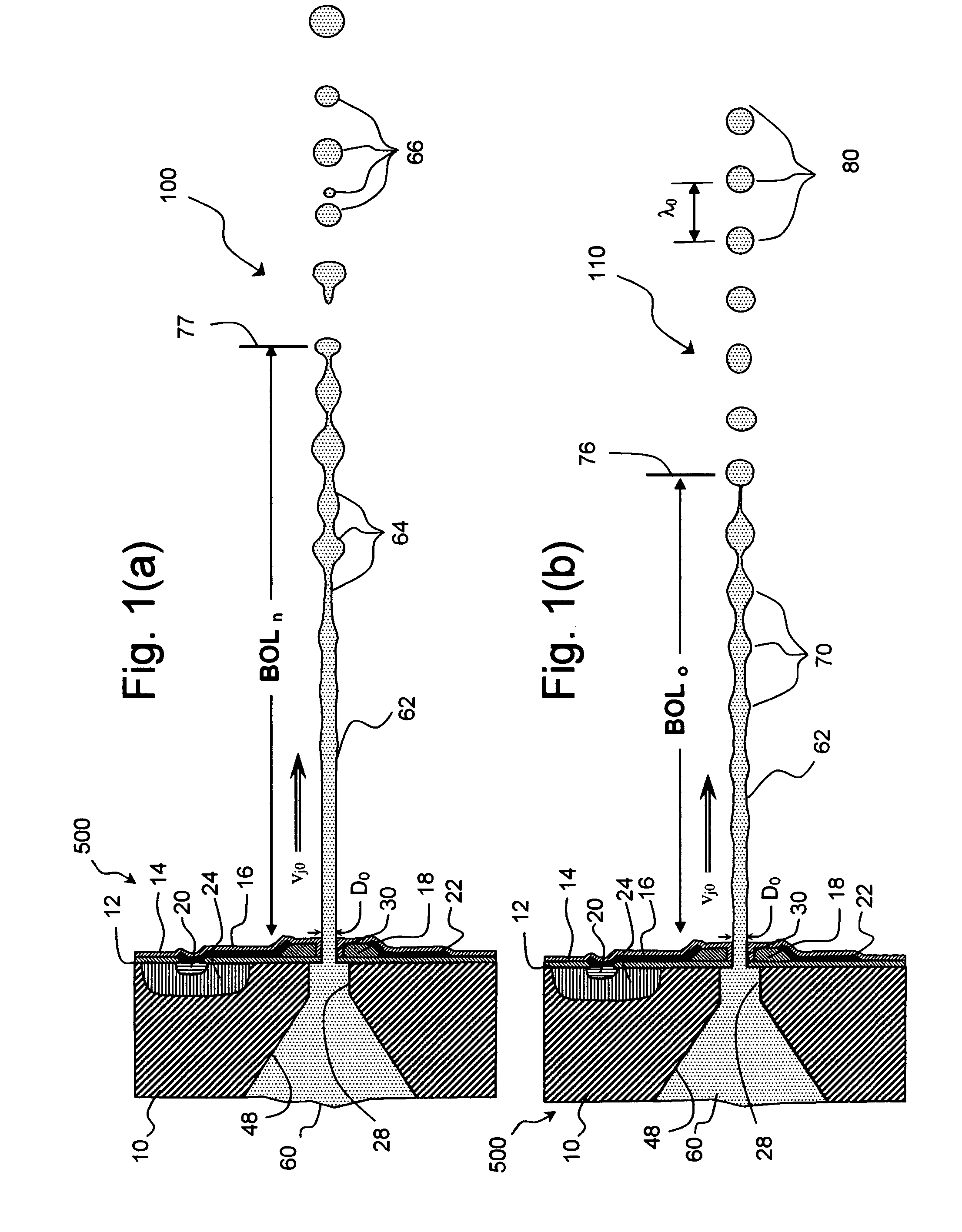
[0048] Referring to FIGS. 1(a) and 11(b), there is shown a portion 500 of a liquid emission apparatus wherein a continuous stream of liquid 62, a liquid jet, is emitted from a nozzle 30 supplied by a liquid 60 held under high pressure in a liquid e...


PUM


Abstract

A drop deposition apparatus for laying down a patterned liquid layer on a receiver substrate, for example, a continuous ink jet printer, is disclosed. The liquid deposition apparatus comprises a drop emitter containing a positively pressurized liquid in flow communication with a linear array of nozzles for emitting a plurality of continuous streams of liquid having nominal stream velocity vj0, wherein the plurality of nozzles have effective nozzle diameters D0 and extend in an array direction with an effective nozzle spacing Ly. Resistive heater apparatus is adapted to transfer thermal energy pulses of period τ0 to the liquid in flow communication with the plurality of nozzles sufficient to cause the break-off of the plurality of continuous streams of liquid into a plurality of streams of drops of predetermined nominal drop volume V0. Relative motion apparatus is adapted to move the drop emitter and receiver substrate relative to each other in a process direction at a process velocity S so that individual drops are addressable to the receiver substrate with a process direction addressability, Ap0S. The effective nozzle spacing is less than 85 microns, the process speed S is at least 1 meter/sec and the addressability, Ap, of individual drops at the receiver substrate in the process direction is less than 6 microns. Drop deposition apparatus is disclosed wherein the predetermined volumes of drops include drops of a unit volume, V0, and drops having volumes that are integer multiples of the unit volume, mV0. Further apparatus is adapted to inductively charge at least one drop and to cause electric field deflection of charged drops.

Description

FIELD OF THE INVENTION [0001] This invention relates generally to continuous stream type drop emitters, especially ink jet printing systems, and more particularly to printheads which stimulate the ink in the continuous stream type ink jet printers by thermal energy pulses and are capable of very high resolution liquid pattern deposition. BACKGROUND OF THE INVENTION [0002] Ink jet printing has become recognized as a prominent contender in the digitally controlled, electronic printing arena because, e.g., of its non-impact, low-noise characteristics, its use of plain paper and its avoidance of toner transfer and fixing. Other applications, requiring very precise, non-contact liquid pattern deposition, may be served by drop emitters having similar characteristics to very high resolution ink jet printheads. By very high resolution liquid layer patterns, it is meant, herein, patterns formed of pattern cells (pixels) having spatial densities of at least 300 per inch in two dimensions. It ...

Claims


Application Information

Patent Timeline
IPC IPC(8): B41J2/07
CPCB41J2/03B41J2002/022B41J2202/16B41J2202/13B41J2002/033
Inventor HAWKINS, GILBERT A.POND, STEPHEN F.
Owner EASTMAN KODAK CO
Why Eureka
Try Eureka