Data encoding apparatus, data decoding apparatus, data encoding method, data decoding method, and recording medium recorded with program

a data encoding and data technology, applied in the field of data encoding apparatus, data encoding apparatus data encoding method, etc., can solve the problems of increasing the probability of a deterioration in compression performance, increasing the use of buffers, and increasing the data size of raw data, so as to achieve favorable compression performance, reduce the amount of required memory, and short processing time

Active Publication Date: 2006-11-23
OLYMPUS CORP
View PDF4 Cites 34 Cited by
  • Summary
  • Abstract
  • Description
  • Claims
  • Application Information

AI Technical Summary

Benefits of technology

[0011] An object of this invention is to provide a data encoding apparatus, a data encoding method, and a recording medium recorded with a program, which are capable of achieving a short processing time, a small amount of required memory, and a favorable compression performance.
[0012] Another object of this invention is to provide a data decoding apparatus, a data decoding method, and a recording medium recorded with a program, which are capable of decoding compressed data in a short processing time and using a small amount of memory.

Problems solved by technology

In recent years, the number of pixels in the image capturing element of a digital camera has increased, leading to an increase in the data size of the RAW data.
However, it is assumed that the RAW data will be retouched by a user, and therefore when compression processing is performed, it is desirable that the compression processing be lossless compression.
It is generally desirable for a compression method to have a high compression ratio, but in the case of a compression method applied to an image capturing apparatus such as a digital camera, in contrast to a compression method applied to a single personal computer or the like, several additional requirements, such as the following, for example, arise from specification limitations and the like.
However, attempts to satisfy both requirement (1) and requirement (2) result in the increased likelihood of a deterioration in the compression performance.
However, with the technique described in U.S. Pat. No. 5,764,374, a table of the appearance frequency and accumulated error must be created for each condition before calculation processing is performed, leading to an increase in buffer use, and hence the aforementioned requirement (2) is not sufficiently satisfied.
Furthermore, the conditions of the peripheral pixels are divided in relation to the encoding target pixel, leading to an increase in processing, and hence requirement (1) is not sufficiently satisfied either.

Method used


Image

  • Data encoding apparatus, data decoding apparatus, data encoding method, data decoding method, and recording medium recorded with program
  • Data encoding apparatus, data decoding apparatus, data encoding method, data decoding method, and recording medium recorded with program
  • Data encoding apparatus, data decoding apparatus, data encoding method, data decoding method, and recording medium recorded with program

Examples


first embodiment

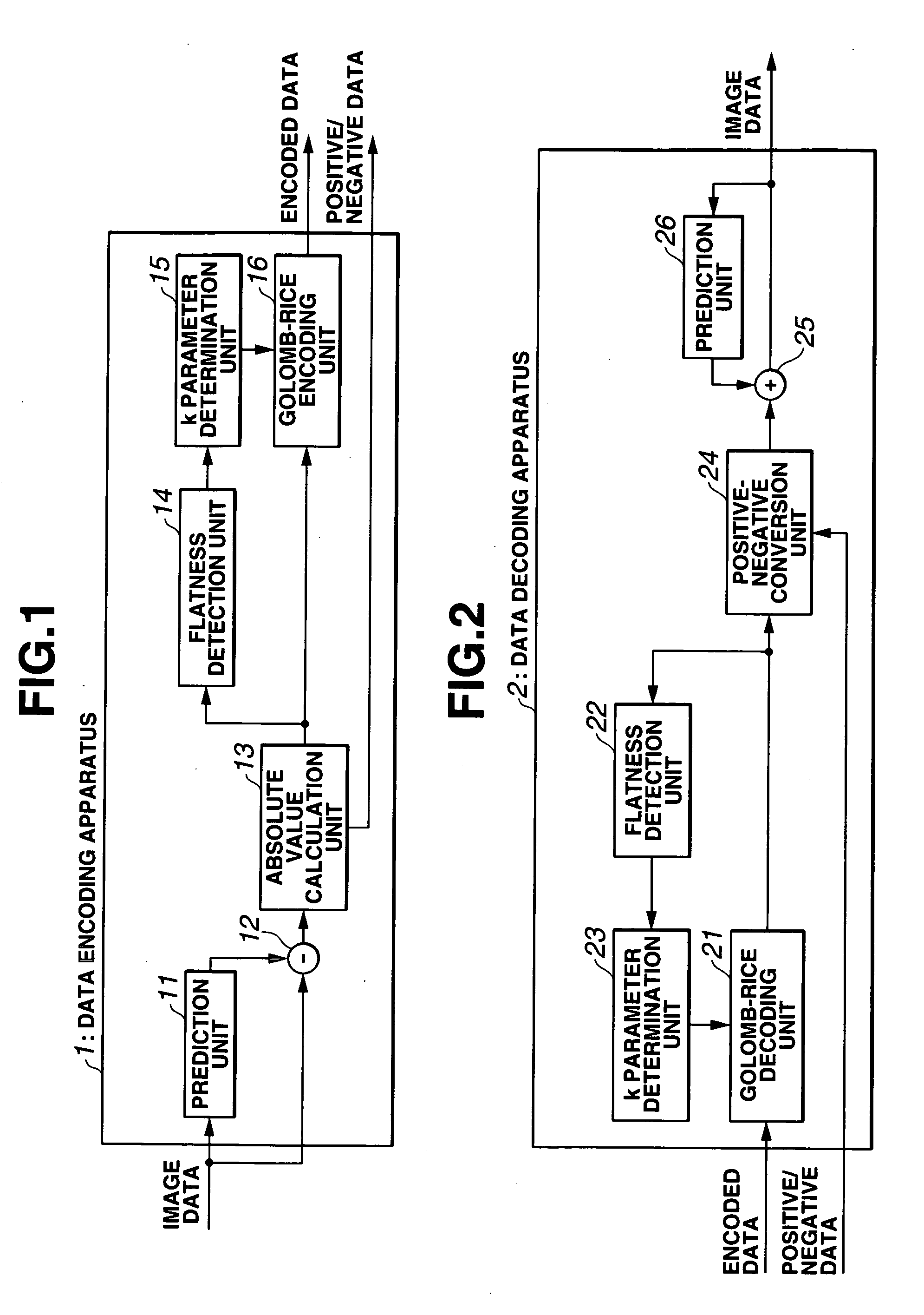
[0055]FIGS. 1 through 27 show a first embodiment of the present invention. FIG. 1 is a block diagram showing the constitution of a data encoding apparatus, and FIG. 2 is a block diagram showing the constitution of a data decoding apparatus.

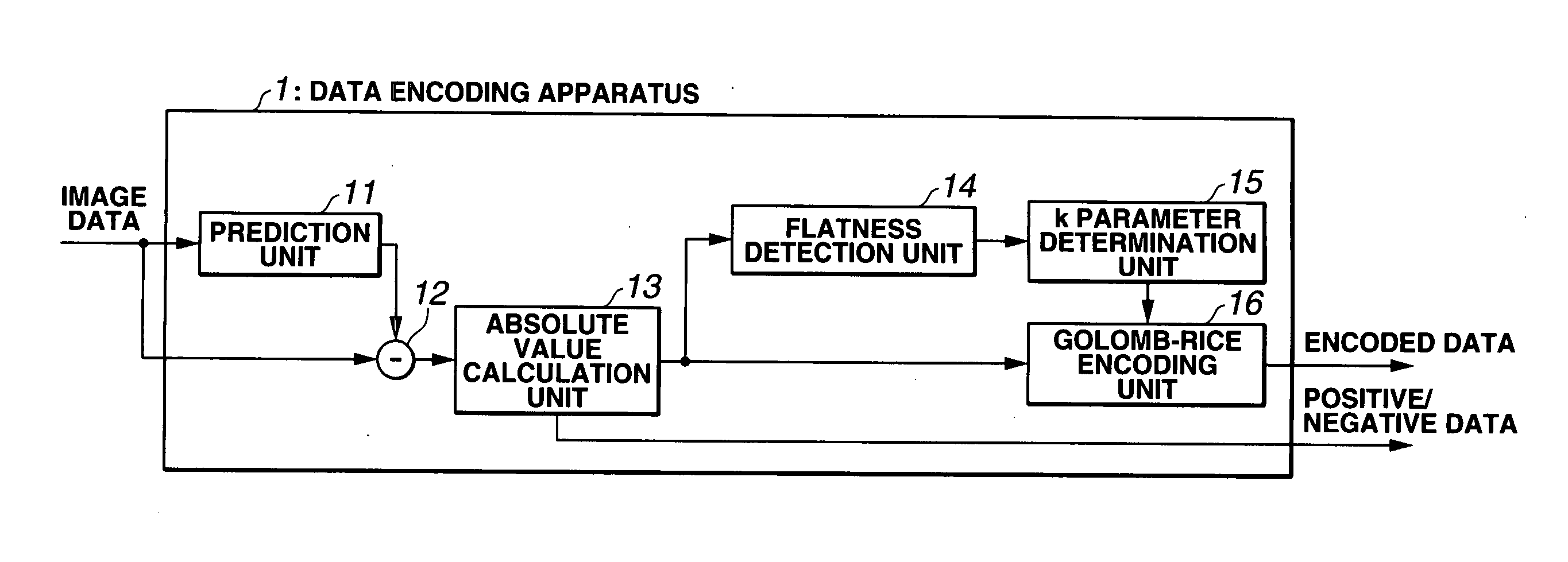
[0056] As shown in FIG. 1, a data encoding apparatus 1 is constituted of a prediction unit 11, a subtractor 12, an absolute value calculation unit 13, a flatness detection unit 14, a k parameter determination unit 15, and a Golomb-Rice encoding unit 16. Image data are input into the prediction unit 11 and subtractor 12, positive / negative data are output from the absolute value calculation unit 13, and encoded data are output from the Golomb-Rice encoding unit 16. The data encoding apparatus 1 will be described in further detail below along the description of actions with reference to FIG. 4, FIGS. 6 through 10, and so on.

[0057] Data compressed by the data encoding apparatus 1 are decoded by a data decoding apparatus 2 as shown in FIG. 2. The dat...

second embodiment

[0155]FIGS. 28 through 34 show a second embodiment of the present invention, in which FIG. 28 is a block diagram showing the constitution of a data encoding apparatus and FIG. 29 is a block diagram showing the constitution of a data decoding apparatus. In the second embodiment, identical reference symbols have been allocated to parts which are similar to those of the first embodiment, and description thereof has been omitted. The following description focuses on different parts.

[0156] A data encoding apparatus 1A of the second embodiment, shown in FIG. 28, has a substantially identical constitution to that of the data encoding apparatus 1 shown in FIG. 1 except that a dynamic range calculation unit 17 is provided in parallel with the flatness detection unit 14, and a k parameter determination unit 15A determines the k parameter using both the detection result of the flatness detection unit 14 and the calculation result of the dynamic range calculation unit 17. The dynamic range cal...


PUM


Abstract

This data encoding apparatus includes: a predictor for calculating a prediction value of target data; a subtractor for calculating the difference between the target data and the prediction value as a prediction error value; an absolute value calculator for calculating the absolute value of the prediction error value; a flatness detector for detecting the number of the absolute prediction error values continuously equal to or lower than a predetermined threshold for some thresholds, and setting a code length candidate for each threshold by comparing the detected number with a predetermined run length; a k parameter determinator for determining the code length of a fixed length code part on the basis of the code length candidate of each threshold; and a Golomb-Rice encoder for encoding the absolute prediction error value in accordance with the determined code length by dividing it into a variable length and the fixed length code parts.

Description

[0001] This application claims benefit of Japanese Application No. 2005-149884 filed in Japan on May 23, 2005, the contents of which are incorporated by this reference. BACKGROUND OF THE INVENTION [0002] 1. Field of the Invention [0003] This invention relates to a data encoding apparatus, a data decoding apparatus, a data encoding method, a data decoding method, and a recording medium recorded with a program, which are used to encode or decode data by separating the data into a variable length code part and a fixed length code part. [0004] 2. Description of Related Art [0005] In an image capturing apparatus such as a digital camera, image capturing data known as RAW data are recorded onto a recording medium in single lens reflex type models and the like, for example. These RAW data are obtained through the implementation of simple analog processing on an image signal obtained from an image capturing element, followed by conversion into digital data. In recent years, the number of pi...

Claims


Application Information

Patent Timeline
Patent Type & Authority Applications(United States)
IPC IPC(8): H04N11/04H04B1/66H04N11/02H04N7/12H03M7/40H04N1/41H04N1/417H04N19/103H04N19/137H04N19/196H04N19/426H04N19/50H04N19/593
CPCH04N19/105H04N19/13H04N19/182H04N19/14H04N19/593
Inventor ISHIKAWA, TAKASHI
Owner OLYMPUS CORP
Why Eureka
Try Eureka