Blood micro-separator

a micro-separator and blood technology, applied in the field of micro-separators, can solve the problem of easy damage of biological specimens, and achieve the effect of low operating efficiency and small volum

Inactive Publication Date: 2006-11-23
NAT CHUNG SHAN INST SCI & TECH
View PDF44 Cites 19 Cited by
  • Summary
  • Abstract
  • Description
  • Claims
  • Application Information

AI Technical Summary

Problems solved by technology

All these would be achieved with difficulties in a conventional reactor.
Because a high voltage has to be used, the biological specimen is easily damaged.
It is only suitable for transporting a continuous fluid.

Method used


Image

  • Blood micro-separator
  • Blood micro-separator
  • Blood micro-separator

Examples


Embodiment Construction

[0032] References are made in detail to the present embodiments of the invention, examples of which are illustrated in the accompanying drawings. Wherever possible, the same reference numbers are used in the drawings and the description to refer to the same or like parts.

[0033] The research and development of disk-like biochemical detection techniques started in around 1990. However, a technological breakthrough was not made until one or two years ago. The leading manufacturers in this area include Gyros, a Swedish company, Tecan and Burstein, two American companies. From 1990 to 2001, the patents issued related to the microfluidic technique include the following: U.S. Pat. No. 4,940,527, U.S. Pat. No. 5,006,749, U.S. Pat. No. 5,061,381, U.S. Pat. No. 5,122,284, U.S. Pat. No. 5,171,695, U.S. Pat. No. 5,173,193, U.S. Pat. No. 5,173,262, U.S. Pat. No. 5,186,844, U.S. Pat. No. 5,242,606, U.S. Pat. No. 5,242,803, U.S. Pat. No. 5,252,294, U.S. Pat. No. 5,275,016, U.S. Pat. No. 5,304,348...


PUM


Abstract

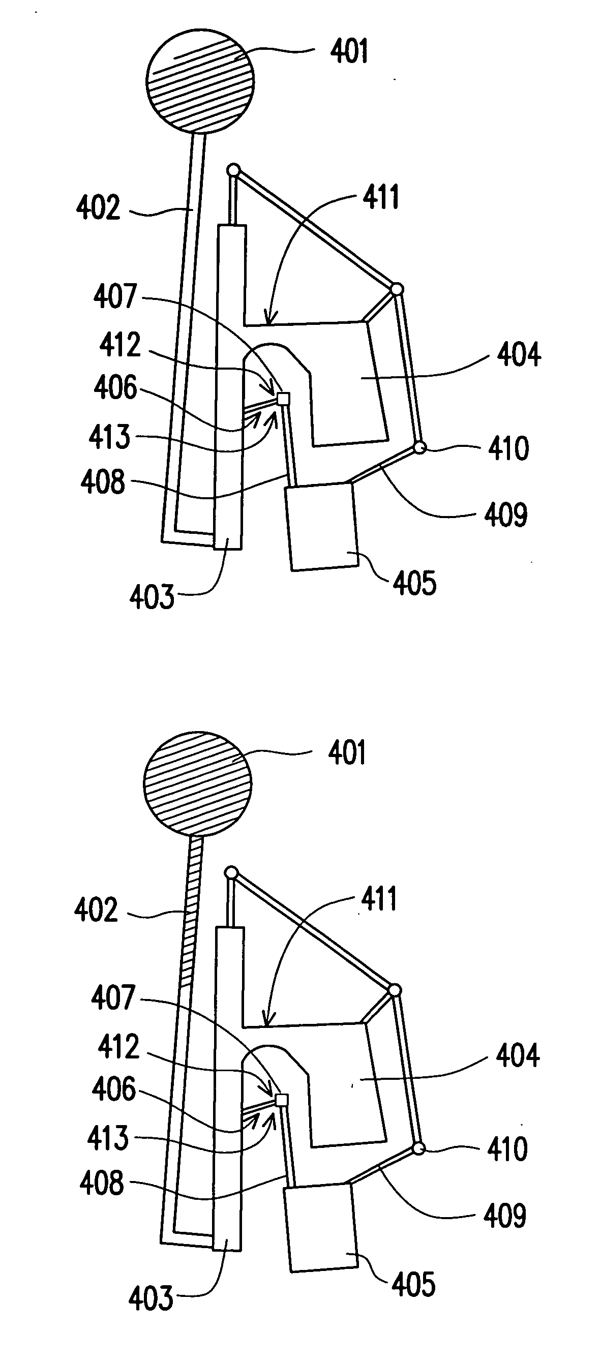
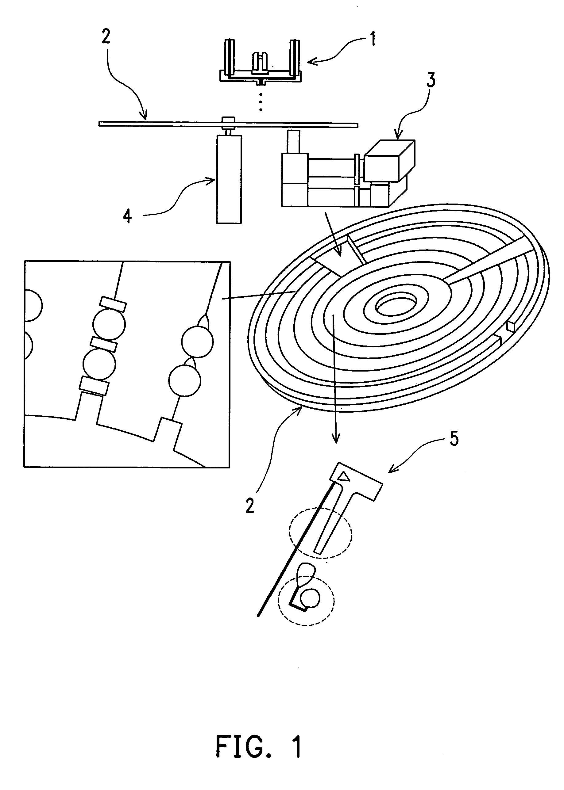
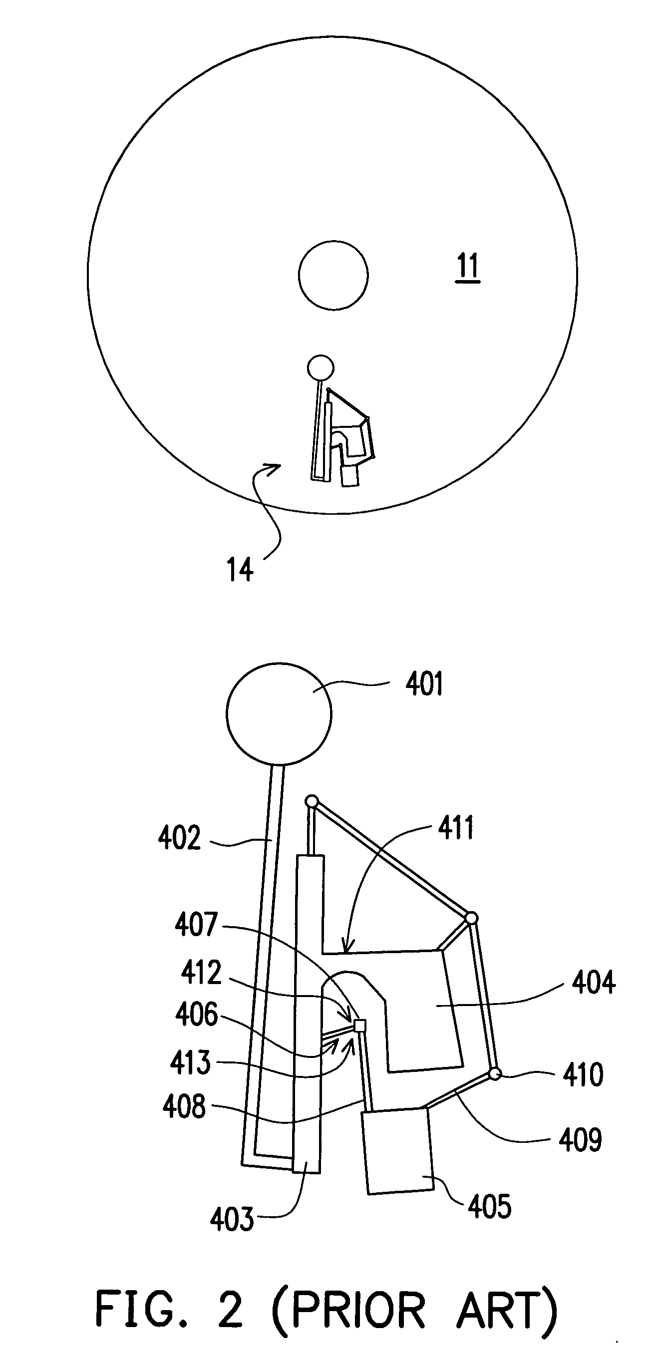
A micro-separator for separating red blood cells from blood serum in a blood sample is provided. The main mechanism driving the separation of the blood sample is centrifugal force. With physical mechanisms including surface tension and functional microstructures, the red blood cells and the blood serum in a small volume of blood (about 25 micro-liters) are separated. The entire micro-separation apparatus is disposed on a disk-shaped structure. The micro-separator can integrate with other micro-devices such as micro-mixers, micro-distributors or micro-reactors to form a fully functional apparatus. Combining the rotary driver of a CD player and an optical inspection device with a signal processing system, an inexpensive, fully automatic, parallel-processing inspection system is produced. The micro-separator has a simple structure with no movable components, and its separation mechanism does not depend on either filter papers or micro-pore structures so blockage is prevented and it can easily combine with other microfluidic devices.

Description

BACKGROUND OF THE INVENTION [0001] 1. Field of the Invention [0002] The present invention relates to a micro-separator for separating blood serum from red blood cells in a blood specimen. The present invention is designed on a round disk similar to a compact disk (CD), utilizing centrifugal force driven by a rotating mechanism in an apparatus such as CD-ROM player, and a valve formed by surface tension between fluid and fluid carrier material, to control the timing of the fluid motion. The micro-separator has a simple structure, small size, without any moving component, and can easily integrate with other related micro-flow devices. [0003] 2. Description of the Related Art [0004] In terms of micro-electronic device development, the major applications and fields that nanometer / micro-electronic technology applies to can be roughly classified into the bio micro-electromechanical system (Bio-MEMS), the radio frequency micro-electromechanical system (RF-MEMS), and the optical micro-elect...

Claims


Application Information

Patent Timeline
Patent Type & Authority Applications(United States)
IPC IPC(8): B01L3/00
CPCB01L3/502707B01L3/502738B01L3/502753B01L2200/0621B01L2400/0688B01L2300/0806B01L2300/0864B01L2300/087B01L2400/0409B01L2200/0684
Inventor KANG, DER-RENYANG, GWEI-CHUHUANG, KER-JERCHAN, CHIH-CHUNWU, HSIEN-MING
Owner NAT CHUNG SHAN INST SCI & TECH
Why Eureka
Try Eureka