Management via dynamic water holdup estimator in a fuel cell

a technology of dynamic water holdup and fuel cell, which is applied in the direction of fuel cells, fuel cell components, fuel cell grouping, etc., can solve the problems of affecting and limiting the performance of the fuel cell stack

Active Publication Date: 2006-11-23
GM GLOBAL TECH OPERATIONS LLC
View PDF12 Cites 70 Cited by
  • Summary
  • Abstract
  • Description
  • Claims
  • Application Information

AI Technical Summary

Problems solved by technology

The level of humidity or hydration of the MEAs affects the performance of the fuel cell.
Too wet of an MEA limits the performance of the fuel cell stack.
Specifically, formation of liquid water impedes the diffusion of gas to the MEAs, thereby limiting their performance.
The liquid water also acts as a flow blockage reducing cell flow and causing even higher fuel cell relative humidity which can lead to unstable fuel cell performance.
Additionally, the formation of liquid water within the cell may cause significant damage when the fuel cell is shut down and exposed to freezing conditions.
That is, when the fuel cell is nonoperational and the temperature in the fuel cell drops below freezing, the liquid water therein will freeze and expand, potentially damaging the fuel cell.
Too dry of an MEA also limits the performance.
Specifically, as the humidity level decreases the protonic resistance of the MEA will start to increase (especially near the inlet), resulting in additional waste heat and lower production of electricity.
Furthermore, durability data suggests that large cycling in the moisture content of the MEA that leads to repeated flooding and drying of membranes can lead to significant loss in durability due to membrane swelling and shrinking.
Thus, repeated flooded and dry operating conditions lead to a loss of overall efficiency and may reduce the durability of the MEA and the fuel cell.
Such strategies, however, do not monitor the state of hydration of the fuel cell and / or fuel cell stack (i.e., how much water buffer is in the membrane, diffusion media and channels).
Additionally, the prior control strategies do not actively manage process excursions that may lead to drying and flooding of the fuel cell and / or fuel cell stack.

Method used


Image

  • Management via dynamic water holdup estimator in a fuel cell
  • Management via dynamic water holdup estimator in a fuel cell
  • Management via dynamic water holdup estimator in a fuel cell

Examples


Embodiment Construction

[0015] The following description of the preferred embodiment is merely exemplary in nature and is in no way intended to limit the invention, its application, or uses.

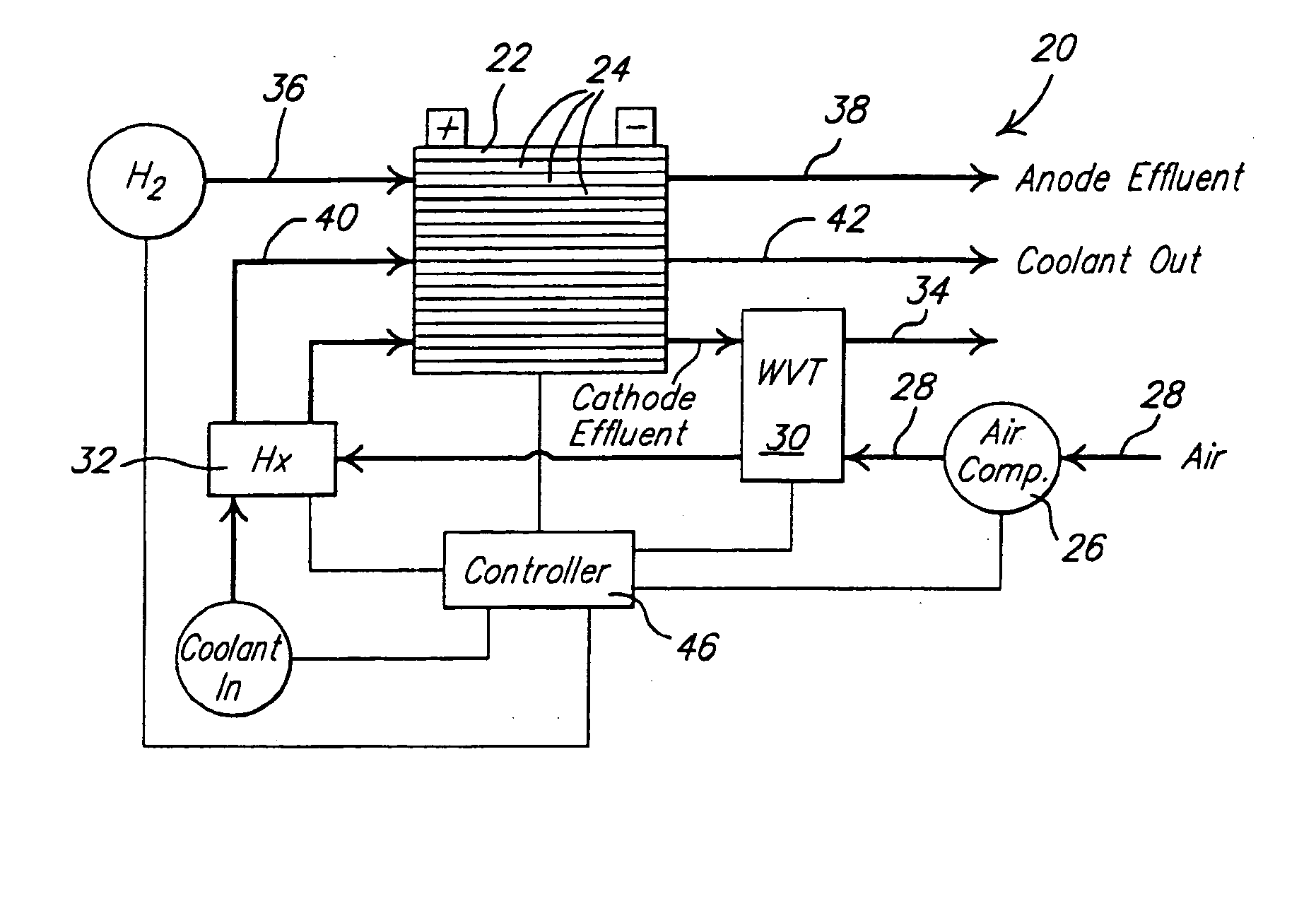
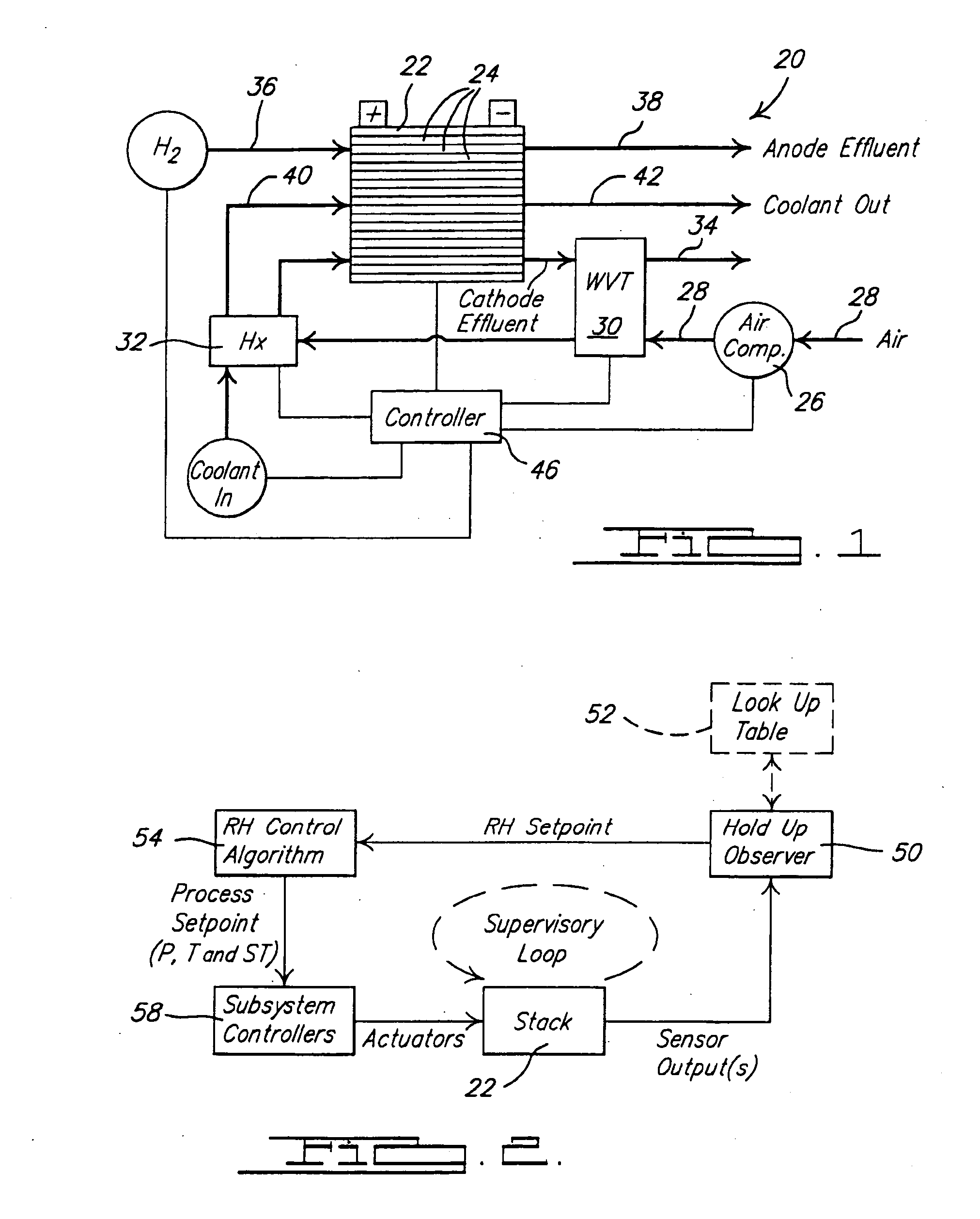
[0016] An exemplary fuel cell system 20 in which the control strategy according to the principle of the present invention can be used is illustrated in FIG. 1. Fuel cell system 20 includes a fuel cell stack 22 which is comprised of a plurality of fuel cells 24 arranged adjacent one another to form stack 22. Fuel cells 24 include membrane-electrode-assemblies (MEAs) separated from each other by electrically conductive, liquid-cooled bipolar separator plates. The fuel cells 24 that are on the ends of stack 22 are disposed between terminal plates and end contact fluid distribution elements. The end fluid distribution elements as well as the working faces or sides of each bipolar plate contain a plurality of lands adjacent to grooves or channels on the active faces and form flow fields (flow paths) for distributing anode a...


PUM

PropertyMeasurementUnit
period of timeaaaaaaaaaa
timeaaaaaaaaaa
voltageaaaaaaaaaa

Abstract

A strategy of controlling a state of hydration of a fuel cell(s) and actively managing operation of the fuel cell(s) to achieve a desired state of hydration. The control strategy monitors the state of hydration and a rate of change of the state of hydration which are used to control the operation of the fuel cell(s). A supervisory control strategy is implemented that alters the operating parameters of the fuel cell(s) based upon the state of hydration, the rate of change of the state of hydration, and a desired operational range for the state of hydration.

Description

FIELD OF THE INVENTION [0001] The present invention relates to fuel cells and, more particularly to controlling the operation of fuel cells based upon a state of hydration of the fuel cells. BACKGROUND OF THE INVENTION [0002] Fuel cells are used as a power source for electric vehicles, stationary power supplies and other applications. One known fuel cell is the PEM (i.e., Proton Exchange Membrane) fuel cell that includes a so-called MEA (“membrane-electrode-assembly”) comprising a thin, solid polymer membrane-electrolyte having an anode on one face and a cathode on the opposite face. The MEA is sandwiched between a pair of electrically conductive contact elements which serve as current collectors for the anode and cathode, which may contain appropriate channels and openings therein for distributing the fuel cell's gaseous reactants (i.e., H2 and O2 / air) over the surfaces of the respective anode and cathode. [0003] PEM fuel cells comprise a plurality of the MEAs stacked together in e...

Claims


Application Information

Patent Timeline
Patent Type & Authority Applications(United States)
IPC IPC(8): H01M8/04
CPCH01M8/04126Y02E60/50H01M8/04335H01M8/04358H01M8/04395H01M8/04455H01M8/04507H01M8/04529H01M8/04559H01M8/04589H01M8/04708H01M8/04723H01M8/04753H01M8/04768H01M8/04835H01M8/0485H01M8/04992H01M8/04223H01M8/241H01M8/04228H01M8/04303H01M8/2457H01M8/0258H01M8/0267H01M8/04302
Inventor SINHA, MANISHFAGLEY, JOHN C.WILLIMOWSKI, PETERGOEBEL, STEVEN G.
Owner GM GLOBAL TECH OPERATIONS LLC
Why Eureka
Try Eureka