Eureka AIR delivers breakthrough ideas for toughest innovation challenges, trusted by R&D personnel around the world.

Fluidic medical devices and uses thereof

a technology of medical devices and fluids, applied in the field of fluid medical devices, can solve the problems of buffers that may leak from holding areas, mix with dry reagents, and become wet or hydrated, and achieve the effect of reducing optical interference and reducing the amount of optical cross-talk

Inactive Publication Date: 2006-11-23
GOLDEN DIAGNOSTICS TOP CORP +2
View PDF98 Cites 103 Cited by
  • Summary
  • Abstract
  • Description
  • Claims
  • Application Information

AI Technical Summary

Benefits of technology

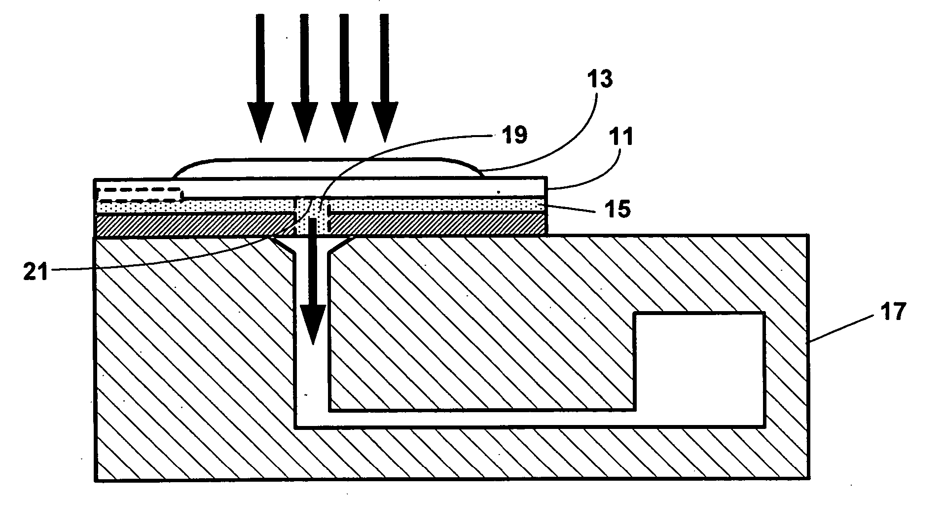
[0008] The present invention provides an apparatus for detecting an analyte in a biological fluid of a subject. The apparatus comprises a sample collection unit for introducing a biological fluid in fluid communication with a plurality of reaction sites, a plurality of reactant chambers carrying a plurality of reactants in fluid communication with said reaction sites wherein said plurality of reaction sites comprise a plurality of reactants bound thereto for detecting said analyte, and a system of fluidic channels to allow said biological fluid and said plurality of reactants to flow in said apparatus, wherein at least one channel located between said plurality of reaction sites comprises an optical barrier to reduce the amount of optical cross-talk between said plurality of said reaction sites during detection of said analyte.

Problems solved by technology

Some challenges in moving such fluids in a fluidic device include mixing the reagents with the sample, and washing unbound reagents from a detection site.
One of the common challenges is washing the unbound conjugates after the incubation period, particularly removing conjugates that remain stuck to the edges of the reaction site walls.
Such a device has several valves and pumps, even if the pumps are not driven by external electrical energy, which are difficult to include in a small disposable fluidic system.
However, dry reagents may become wet or hydrated before they are intended to do so.
Buffers may leak from their holding areas and mix with the dry reagents.
A bubble introduced into the system can cause an inaccurate measurement if the bubble is located in the detection site during the detection step.
This problem may become worse the longer the incubation time of the assay.

Method used


Image

  • Fluidic medical devices and uses thereof
  • Fluidic medical devices and uses thereof
  • Fluidic medical devices and uses thereof

Examples


Embodiment Construction

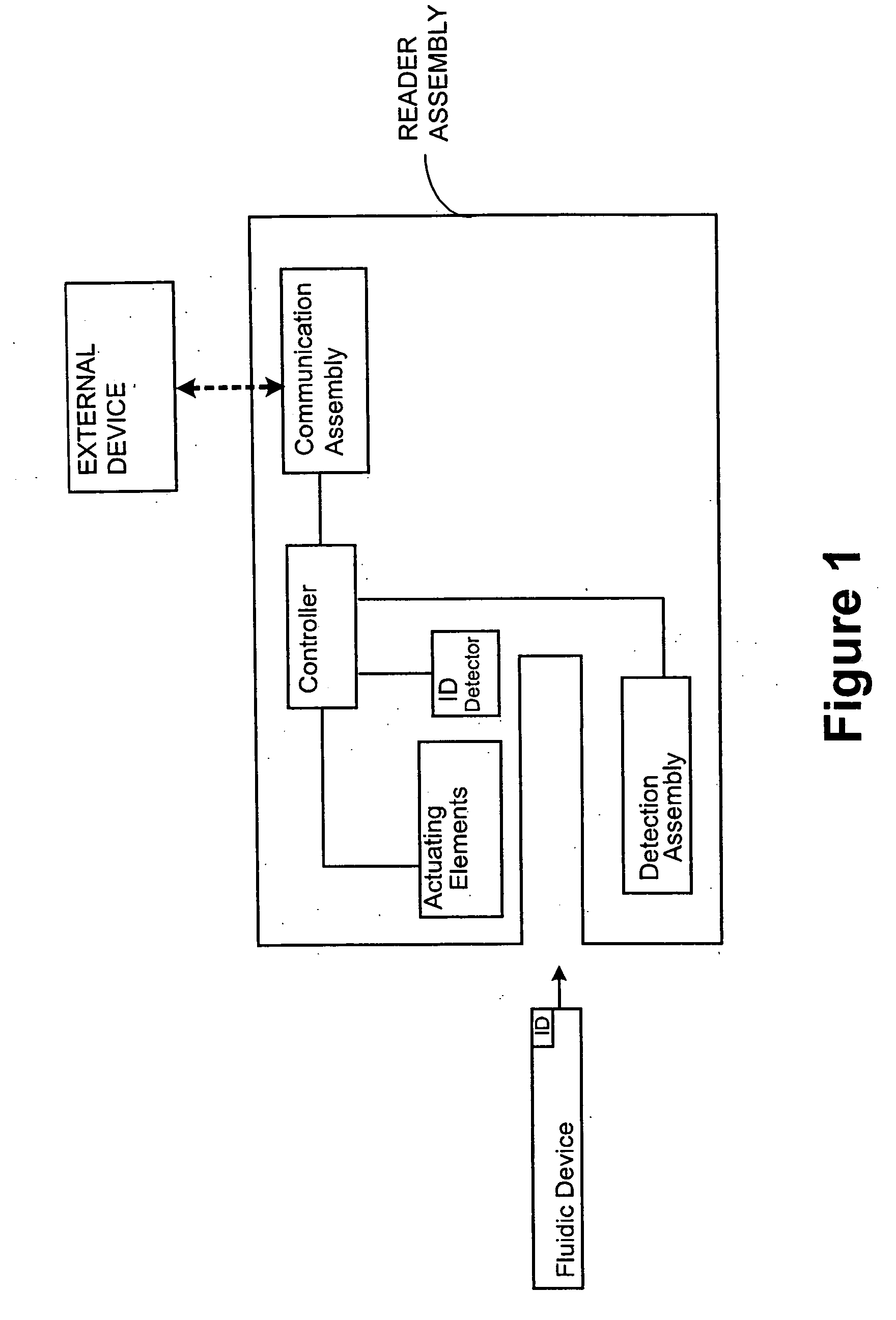
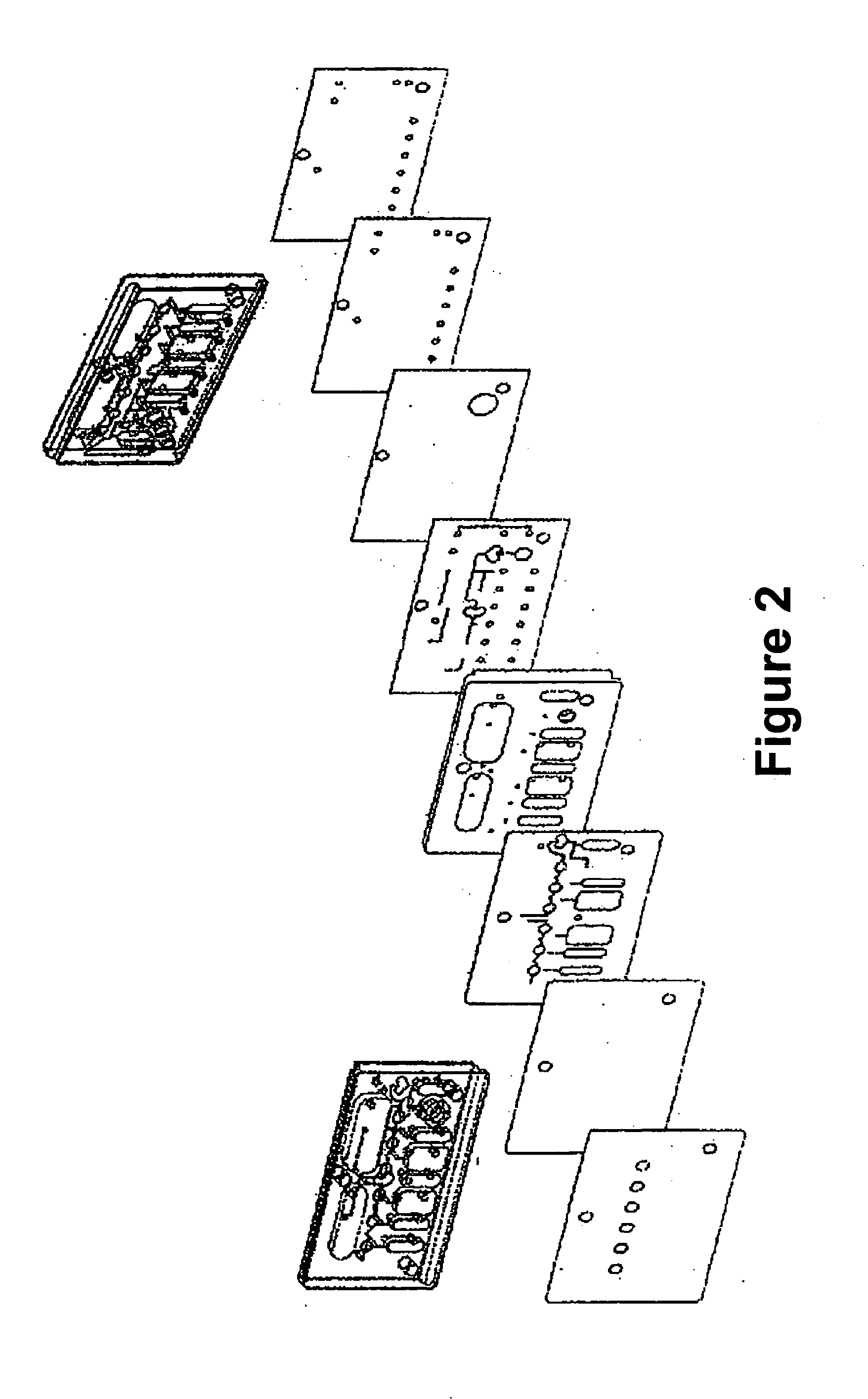
[0027] One aspect of the present invention is a system for detecting an analyte in a sample of bodily fluid. The subject system has one or more of the following components: a) a sample collection unit for introducing a biological fluid in fluid communication with a plurality of reaction sites, b) a plurality of reactant chambers carrying a plurality of reactants in fluid communication with said reaction sites wherein said plurality of reaction sites comprise a plurality of reactants bound thereto for detecting said analyte, and c) a system of fluidic channels to allow said biological fluid and said plurality of reactants to flow in said apparatus, wherein at least one channel located between said plurality of reaction sites comprises an optical barrier to reduce the amount of optical cross-talk between said plurality of said reaction sites during detection of said analyte.

[0028] Where desired, the system may further comprise a reader assembly and a communication assembly. The sampl...


PUM


Abstract

This invention is in the field of medical devices. Specifically, the present invention provides fluidic systems having a plurality of reaction sites surrounded by optical barriers to reduce the amount of optical cross-talk between signals detected from various reaction sites. The invention also provides a method of manufacturing fluidic systems and methods of using the systems.

Description

CROSS-REFERENCE [0001] This application claims the benefit of U.S. Provisional Application No. 60 / 678,801, filed May 9, 2005 and U.S. Provisional Application No. 60 / 705,489, filed Aug. 5, 2005 and U.S. Provisional Application No. 60 / 717,192, filed Sep. 16, 2005, and U.S. Provisional Application No. 60 / 721,097, filed Sep. 28, 2005 which are incorporated herein by reference in their entirety.BACKGROUND OF THE INVENTION [0002] Point-of-Care (POC) testing systems and fluidic devices or cartridges are becoming more common because of the advancement in microfabrication technology such as MEMS technology, which enables the fabrication of reliable and inexpensive fluidic based cartridges. Generally, such systems use microvalves, micropumps, microneedles, etc. for moving the fluids through the fluidic system. A common system contains a reagent reservoir, a mixing chamber, an analytical chamber and waste chamber. Fluids must therefore be moved from one chamber to another. Some challenges in m...

Claims


Application Information

Patent Timeline
IPC IPC(8): A61B5/00
CPCA61B5/1411Y10T436/10A61B5/412A61B5/417G01N33/50A61B5/1427A61B5/14546A61B5/1495G01N33/5302B01L2300/0816B01L2300/087B01L2300/021B01L2300/023B01L2300/0887B01L2300/044B01L2300/0867B01L2300/0636B01L2300/0883B01L2300/0877B01L3/50273G06F19/3406A61B5/150022A61B5/150099A61B5/150251A61B5/150854A61B5/15142A61B5/157Y10T436/143333Y10T436/115831Y10T436/11Y10T436/12A61B5/14532A61B5/150763G16H40/63G01N33/53G01N2500/00Y02A90/10G01N21/76G01N33/54386B01L2300/0861
Inventor KEMP, TIMOTHY M.TODD, CHRISORAL, RONZENG, SHULINHOWARD, JOHNFENTON, JEFF
Owner GOLDEN DIAGNOSTICS TOP CORP
Why Eureka
Eureka Blog
Learn More