Low profile system for joining optical fiber waveguides

a technology of optical fiber waveguides and low profile, applied in the direction of glass making apparatus, testing of fibre optic/optical waveguide devices, structural/machine measurement, etc., can solve the problems of difficult repair access, affecting the repair process, so as to minimize the loss of spliced fibers, the effect of low profile and low profil

Inactive Publication Date: 2006-11-30
AURORA INSTR
View PDF36 Cites 14 Cited by
  • Summary
  • Abstract
  • Description
  • Claims
  • Application Information

AI Technical Summary

Benefits of technology

[0021] The present invention provides a low profile system for joining optical fibers by fusion splicing. The system is preferably modular and low profile, enabling it to be used to form low transmission loss splices under difficult field conditions. The loss of spliced fibers is preferably minimized by use of automatically driven, active optical systems for adaptively aligning the cores of the two fibers prior to fusion. Such systems in some embodiments employ a profile alignment (PAS) system that employs a compact, imaging optical system incorporated in a fusion splicing head of the system. More preferably, embodiments of the system further incorporate a low profile local injection and detection (LID) system in carrying out the alignment. In the LID technique, optimal alignment is signaled by maximization of the transmission of light across the interface between the fibers. The LID system further allows the transmission loss of the spliced fiber to be accurately inferred.

Problems solved by technology

In the telecommunications industry, repairs frequently must be made to overhead lines by a technician operating from a ladder, lift bucket, sometimes during darkness and with adverse weather conditions such as precipitation, cold, and wind.
Cables in these locations are often routed through tight quarters, some in hazardous locations, making access for repair difficult.
Communication systems on ships and in airplanes and spacecraft likewise advantageously employ fiber optic transmission; cable routing and access are often comparably problematic in these applications.
In most of the aforementioned situations repair is further hampered because of the limited length of slack in the fiber that may be accessible for the technician to manipulate into a splicing device.
Alignment of fibers is a crucial part of the preparation for any splicing operation, but is especially challenging for single mode fibers that have small core diameter.
However, even in the best case, a mechanical splice has relatively high and undesirable insertion loss, typically 0.20 dB.
In addition, mechanical splices are generally weaker than the underlying fiber and are notoriously vulnerable to degradation of the optical quality of the splice over time, especially under adverse environmental conditions such as varying temperatures and high humidity.
Mechanical splices are generally regarded as being temporary expedients at best and are not useful for high bandwidth systems or permanent joints.
This required precision of alignment presents a substantial technical challenge, especially with single-mode fibers having cores approximately 9 μm diameter.
These purely mechanical approaches do not reliably produce splices that maintain less than 0.10 dB loss and so are ill suited for the demands of advanced, high-bandwidth communications systems.
However, the diffraction limit and pixel size of available electro-optic detectors restricts the precision achievable with PAS, even in systems based on visible light with wavelengths of about 400-700 nm.
This particularly compromises the effectiveness of PAS in aligning small diameter, single mode fibers.
However, the methods and apparatus for carrying out splicing aided either by the PAS or by transmission-based alignment techniques have heretofore not been well suited for use outside the laboratory or other similarly controlled workplace.
The required equipment lacks the flexibility, versatility, and ruggedness needed for field use.
Moreover, present equipment is cumbersome and not operable in the confined spaces frequently encountered during field service.

Method used


Image

  • Low profile system for joining optical fiber waveguides
  • Low profile system for joining optical fiber waveguides
  • Low profile system for joining optical fiber waveguides

Examples


Embodiment Construction

[0054] The present invention is directed to a compact, low profile apparatus and system for joining optical fiber waveguides to produce a durable fusion splice between a first and a second optical fiber. The joined fiber advantageously exhibits low attenuation. Advantageously the present system employs an adaptive technique to optimize the alignment of the fibers prior to fusion, whereby the insertion loss of the splice is minimized.

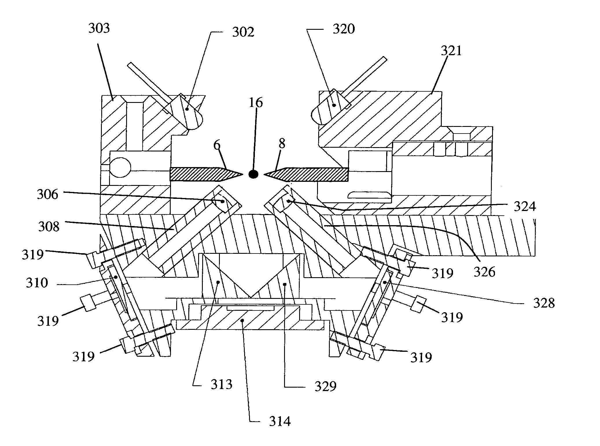
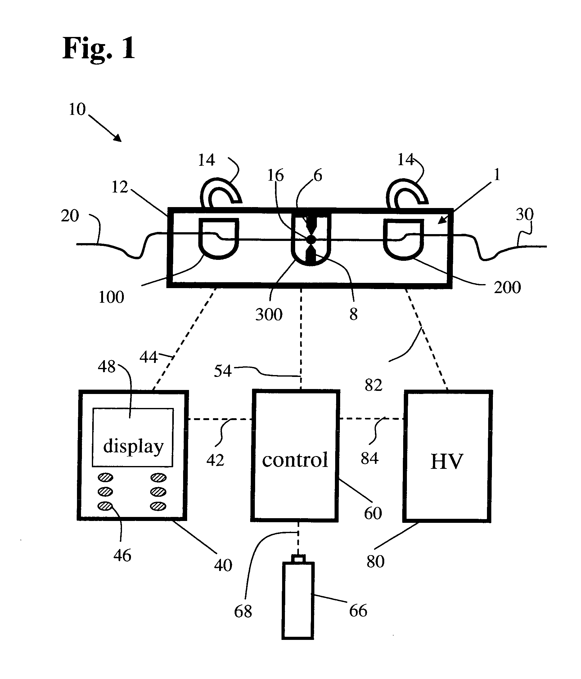
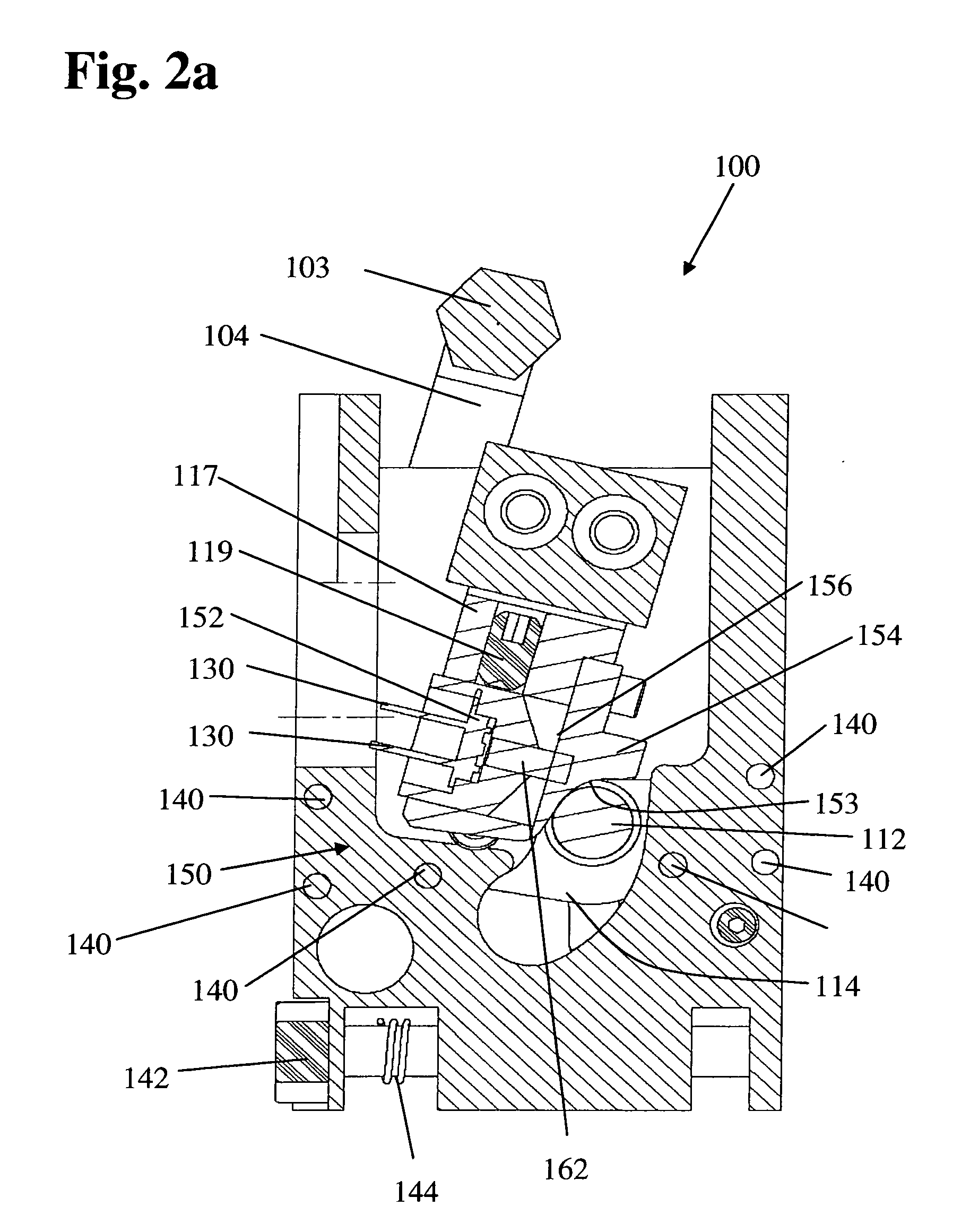
[0055] Referring now to FIG. 1 there is depicted generally an implementation of a modular, low profile fusion splicing system 10 of the invention. Fusion splicing head 1 of the invention incorporates a local injection and detection system. First and second optical fibers 20, 30 are positioned in light injector 100 and light detector 200, aspects of which are depicted in greater detail by FIGS. 2A-2B and 3A-3B, respectively. The free ends of the fibers 20, 30 appointed to be joined are situated in facing, collinearly aligned relationship in fusion splici...


PUM

PropertyMeasurementUnit
wavelength rangingaaaaaaaaaa
diametersaaaaaaaaaa
diameteraaaaaaaaaa

Abstract

A compact, low profile splicing system for joining optical fibers produces durable, low transmission loss fusion splices. The system employs active optical techniques such as profile alignment or local injection and detection to achieve optimized alignment of the fibers prior to fusion. Light injected into one fiber is propagated across the interface to a second fiber. A detector senses the intensity of the injected light in the second fiber. After the relative position of the fibers is manipulated to maximize the transmitted intensity, the fibers are fusion spliced using an electric arc discharge. The accurate alignment achievable using the local injection and detection system to drive adaptive fiber positioning affords a method for reliably producing low loss splices. The present system is compact and low in profile, making it operable in cramped quarters with limited clearance to adjacent equipment and structures and with only a minimal amount of free fiber slack available. Simplicity of design and operation make the system rugged and enable accurate alignment and low loss fusion of fibers under adverse working conditions.

Description

[0001] This application claims the benefit of application No. 60 / 456,915, filed Mar. 24, 2003.BACKGROUND OF THE INVENTION [0002] 1. Field of the Invention [0003] This invention relates to an apparatus for joining optical fiber waveguides; and more particularly, to a low profile system that adaptively positions the fibers being joined prior to fusion splicing, so that the transmission loss of the joined fiber is minimized. [0004] 2. Description of the Prior Art [0005] Transmission of data by optical fiber waveguides, also called fiber optics or optical fibers, has become ubiquitous in the telecommunications and computer industries. Digital information in an electronic system is converted into a series of pulses of light generated by lasers or light emitting diodes (LED's), which are injected into long fibers of glass or polymeric materials. The fibers are capable of propagating the light with extremely low losses and acceptably low dispersion, whereby information embodied in the modu...

Claims


Application Information

Patent Timeline
Patent Type & Authority Applications(United States)
IPC IPC(8): C03B37/15G02B6/255G01M11/00G02B6/38
CPCG01M11/37G02B6/2555G02B6/2551
Inventor BUSH, SIMON P.CABATO, NELLIE L.CROWELL, JOHN A.MA, CHENG P.VELLRATH, ANDREWWESSON, LAURENCE N.
Owner AURORA INSTR
Why Eureka
Try Eureka