

Power distribution system and load management protocol therefor
- Summary
- Abstract
- Description
- Claims
- Application Information
AI Technical Summary
Benefits of technology
Problems solved by technology
Method used
Image

Examples
Embodiment Construction
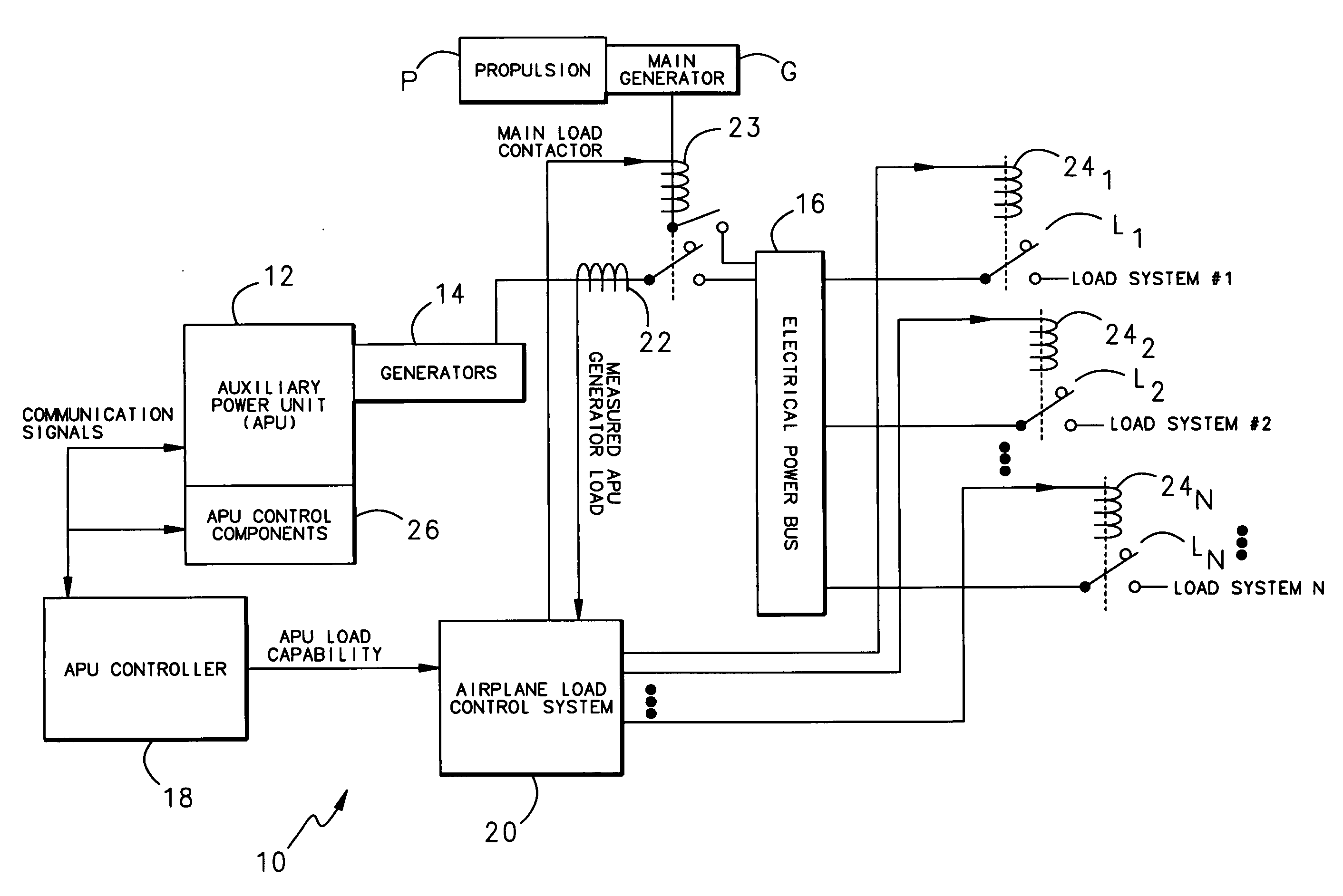
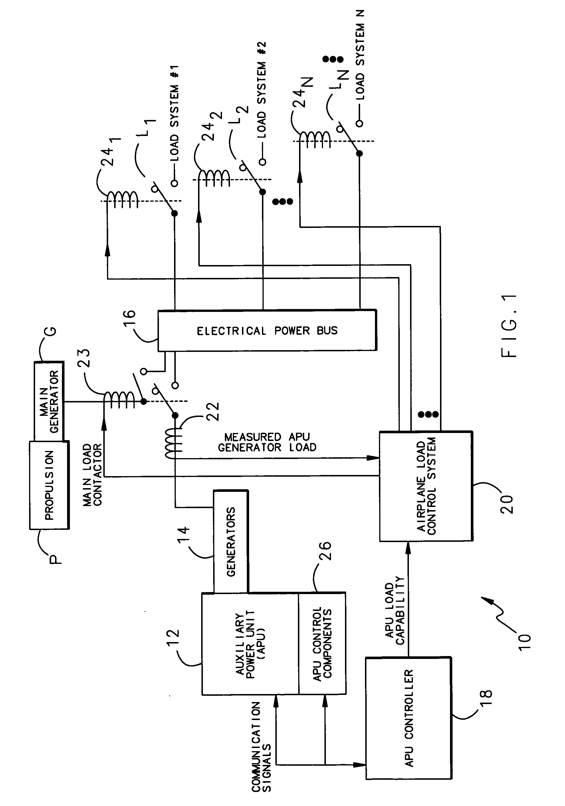
[0016]FIG. 1 illustrates a general schematic block diagram of a power distribution system 10. Power distribution system 10 is preferably a system which operates as an additional power source for a “more electric” aircraft. It should be understood, however, that the Power distribution system 10 may be utilized in other applications, such as in a stationary generating station or ground power unit used to service aircrafts.
[0017] The power distribution system 10 generally includes an Auxiliary Power Unit (APU) 12 which drives a generator 14 to power a multitude of loads L1-Ln through a power bus 16. The APU 12 is controlled through an APU controller 18 which communicates with an aircraft load controller 20.
[0018] The APU 12 is preferably a gas turbine engine separate from a primary propulsion engine P such as an aircraft turbofan engine. Electrical loads L1-Ln are normally powered within the power distribution system 10 including primary generator G, which in turn is typically driven...
PUM
 Abstract
Description
Claims
Application Information