Magnetic resonance device with attachment means for attaching a gradient coil, attachment means

a gradient coil and magnetic resonance technology, applied in the field of magnetic resonance devices, to achieve the effect of preventing the loosening of the wedge system, reducing the surface pressure, and ensuring the stability of the coil

Inactive Publication Date: 2006-11-30
SIEMENS HEALTHCARE GMBH
View PDF7 Cites 2 Cited by
  • Summary
  • Abstract
  • Description
  • Claims
  • Application Information

AI Technical Summary

Benefits of technology

[0007] The object of the invention is to create an attachment for a gradient coil, which satisfies the stringent requirements during operation of a magnetic resonance device over a long period of time.
[0010] One advantage of the attachment according to the invention is that even if the dimensions of the gradient coil unit or member change due to thermal conditions, loosening of the wedge system is prevented in that the attachment means remain spatially fixed with the aid of the spring force of the elastic element, even in the thermally expanded state. This prevents local working and micro-movement of the wedges, which would cause loosening. The attachment means preferably have a large contact surface both at the gradient coil unit and on the inside of the assembly, to achieve the smallest possible surface pressure. The surface contact of the surfaces of the attachment means should also thereby be maximized as far as possible (conical contact surfaces of the gradient coil unit and the attachment means), to ensure a reliable fix with long-term stability. The transmission of vibration from the gradient coil unit to the external components can also be specifically prevented using the wedge geometry.

Problems solved by technology

This prevents local working and micro-movement of the wedges, which would cause loosening.

Method used


Image

  • Magnetic resonance device with attachment means for attaching a gradient coil, attachment means
  • Magnetic resonance device with attachment means for attaching a gradient coil, attachment means
  • Magnetic resonance device with attachment means for attaching a gradient coil, attachment means

Examples


Embodiment Construction

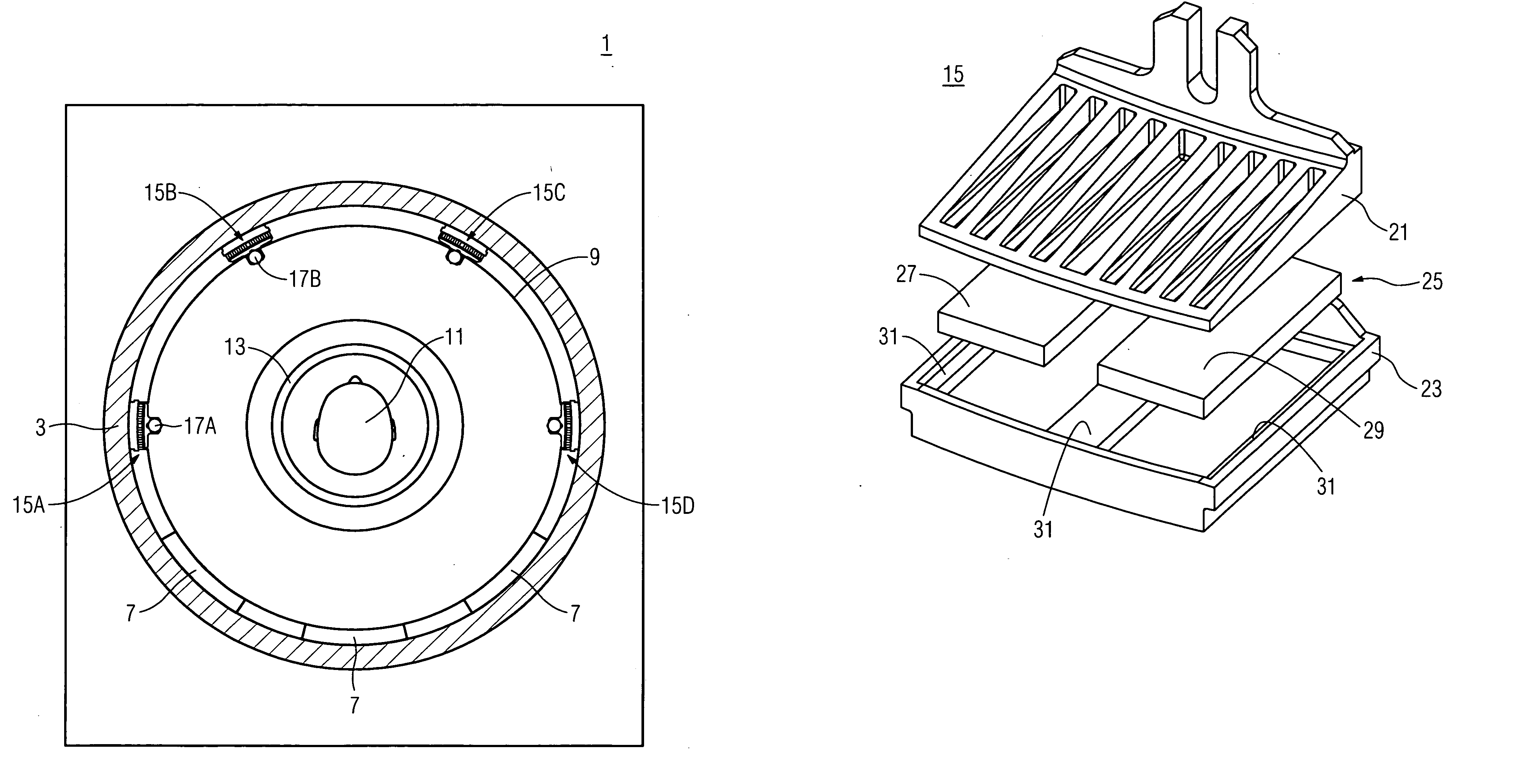
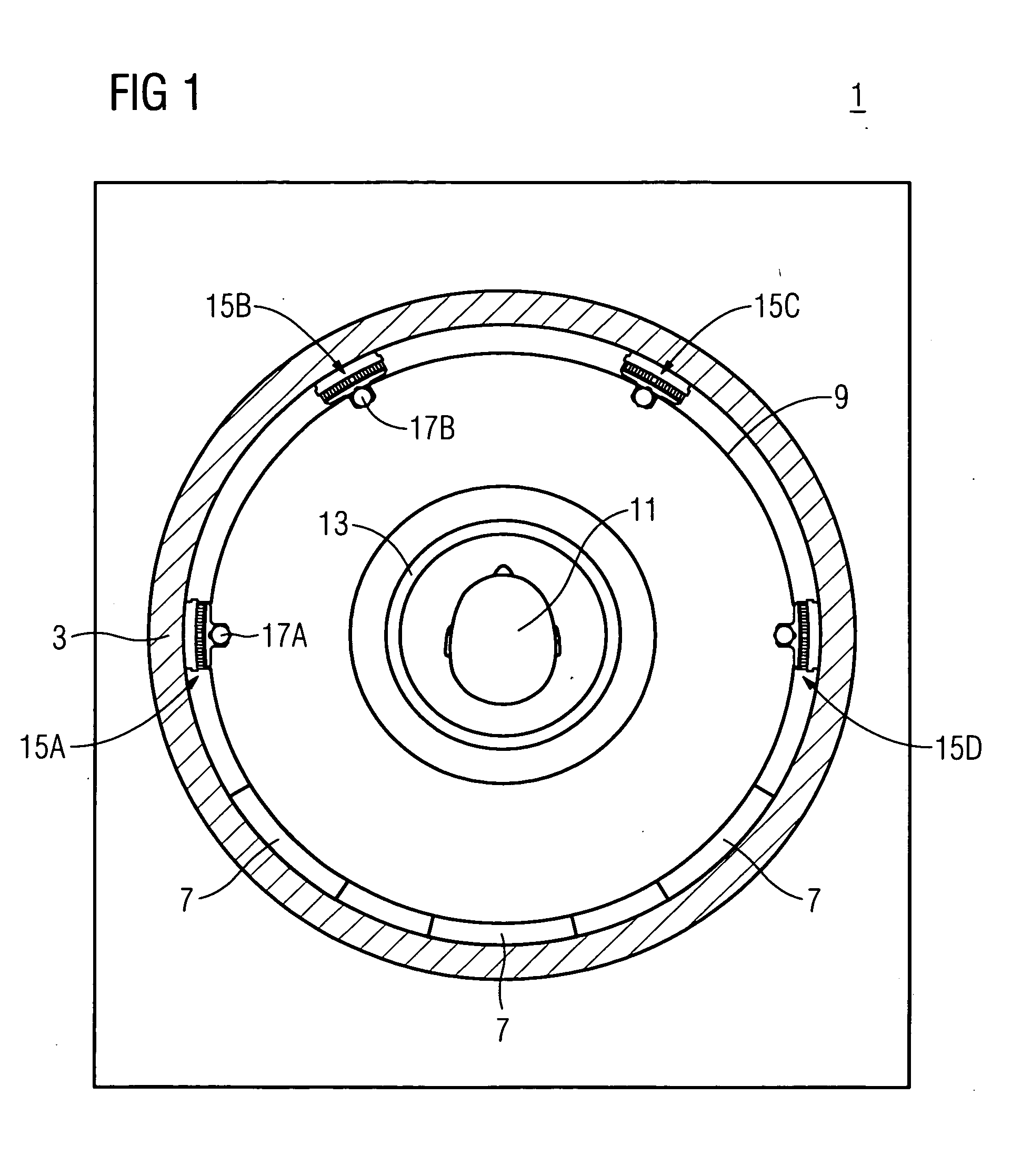
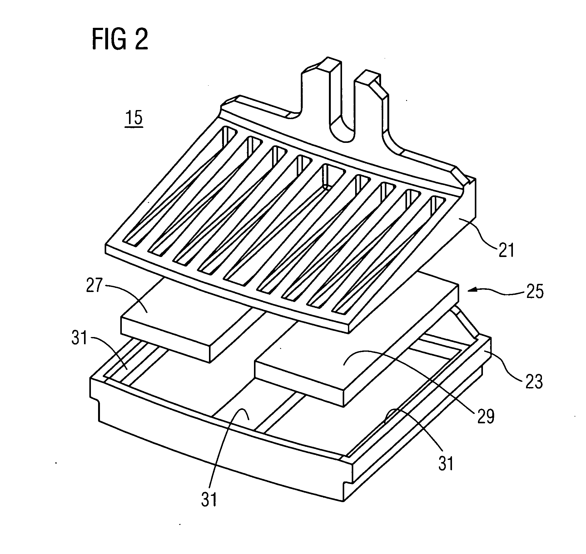
[0017]FIG. 1 shows a front view of a magnetic resonance device 1 with an assembly 3, for example a basic field magnet of the MR device 1. The assembly 3 encloses an examination area 5, which is configured in a cylindrical manner as a recess in the magnetic resonance device 1. A gradient coil unit 9 is disposed in this recess on layers 7 of an elastic material. The gradient coil unit 9 is for example made of glass fiber in an epoxy resin matrix and copper; the weight of the gradient coil unit is then approx. 750 kg. The gradient coil unit is fixed with the aid of attachment means 15A, . . . 15D, which are disposed in the upper area of the resulting annular gap between the gradient coil unit 9 and the assembly 3 and of which four are shown by way of an example in FIG. 1. For attachment purposes the attachment means 15A, . . . 15D are driven into the gap at both ends of the gradient coil unit 9 and screwed into place with screws 17A such that the attachment means 15A, . . . 15D are jam...


PUM


Abstract

Magnetic resonance device (1) with an assembly (3) having a recess, in which a gradient coil unit (9) is attached with at least one attachment means (15, . . . 15D), the attachment means (15 ... 15D) having two members (21,23), between which an elastic element (25) is disposed, only one of the members (21,23) in each instance being in contact with either the gradient coil unit (9) or the assembly (3), with the attachment means (15, . . . 15D) acting as an attachment means (15, . . . 15D) having no elastic element (25) in a first attachment state, in which at least a minimum force (FMIN) presses the two members (21, 23) together, in that the two members (21, 23) have stop surfaces (31), which are in contact with each other due to the minimum force acting on the members (21, 23) [lacuna] compressed elastic element (25) and with the attachment means (15, . . . 15D) acting as a spring unit in a second fixing state, in that the elastic element (25) pushes the members (21, 23) apart in the event of forces smaller than the minimum force (FMIN) and causes the attachment means (15, . . . 15D) to be fixed in relation to the gradient coil unit (9) and the assembly (3). This has the advantage that there is no loosening of the attachment means in particular even in the event of thermal fluctuations.

Description

CROSS REFERENCE TO RELATED APPLICATIONS [0001] This application claims priority of German application No. 10 2005 025 339.3 filed May 31, 2005, which is incorporated by reference herein in its entirety. FIELD OF THE INVENTION [0002] The invention relates to a magnetic resonance device with an assembly having a recess, in which a gradient coil unit is attached with attachment means. The invention also relates to attachment means for such an attachment. BACKGROUND OF THE INVENTION [0003] Magnetic resonance technology (MR technology) is a known technology, for example for obtaining cross-sectional images of an examination subject using nuclear magnetic resonance signals. Rapidly switched gradient fields, which are generated by a gradient coil unit, are thereby superimposed in a magnetic resonance device on a static basic magnetic field, which is generated by a basic field magnet. The magnetic resonance device also comprises a high-frequency system, which radiates high-frequency signals...

Claims


Application Information

Patent Timeline
Patent Type & Authority Applications(United States)
IPC IPC(8): G01V3/00
CPCG01R33/385G01R33/28
Inventor DIETZ, PETERKOLBECK, THOMASRIEGLER, JORGSCHUSTER, JOHANNSCHON, LOTHARSTOCKER, STEFAN
Owner SIEMENS HEALTHCARE GMBH
Why Eureka
Try Eureka