
Mox fuel assembly for pressurized water reactors

a technology of pressurized water and mox fuel, which is applied in the direction of nuclear reactors, greenhouse gas reduction, nuclear elements, etc., can solve the problems of increasing the total manufacturing cost of preparing the necessary fuel assembly, not reaching a fundamental solution, and the three-stage content distribution type mox fuel assembly has a drawback of increased manufacturing cost and other problems

Inactive Publication Date: 2006-11-30
NUCLEAR FUEL INDS
View PDF3 Cites 8 Cited by
  • Summary
  • Abstract
  • Description
  • Claims
  • Application Information

AI Technical Summary

Benefits of technology

[0015] Therefore, a problem of this invention is to provide a MOX fuel assembly for PWRs that enables satisfactory control of the power peaking factor within the fuel assembly without the necessity of reducing a Pu content per fuel assembly by designing properly arrangement of individual fuel rods within the MOX fuel assembly.
[0021] In the MOX fuel assembly according to a preferred embodiment of this invention, the first MOX fuel rod and the second MOX fuel rod each contain the same number of MOX fuel pellets confined in the respective cladding tubes, the both MOX fuel pellets being substantially equal in height dimension and in Pu content. In this case, the first MOX fuel pellet confined in the first MOX fuel rod and the second MOX fuel pellet confined in the second MOX fuel rod are different from each other in Pu weight. The difference in Pu weight between the first MOX fuel pellet and the second MOX fuel pellet may be realized by differentiating weights of the both pellets. When forming these pellets from raw powder of the same Pu content, this condition can be achieved by the following techniques: the diameter and / or the density of one of the two pellets is adjusted comparatively to the other pellet; or one or both of the two pellets are provided with a hole (hollow pellet) and the volume of this hole is adjusted relatively. It is possible to obtain plural kinds of MOX fuel pellets that are different from one another in Pu weight by differentiating the weights of the first MOX fuel pellet and of the second MOX fuel pellet in this way. In this case, management of the fuel materials, such as collection of forming dust in a line, and process management become simple because a fuel material handled in the manufacturing line of the MOX fuel rods is the same material of a single Pu content. Moreover, even when fabricating plural kinds of MOX fuel rods, the manufacture can easily be applied to these MOX fuel rods only by replacing a forming mold used in a pellet formation step by another mold of a different shape, or by adjusting forming pressure. Therefore, this technique can bring an advantage that increase in the manufacturing cost can be controlled to be a negligible amount.
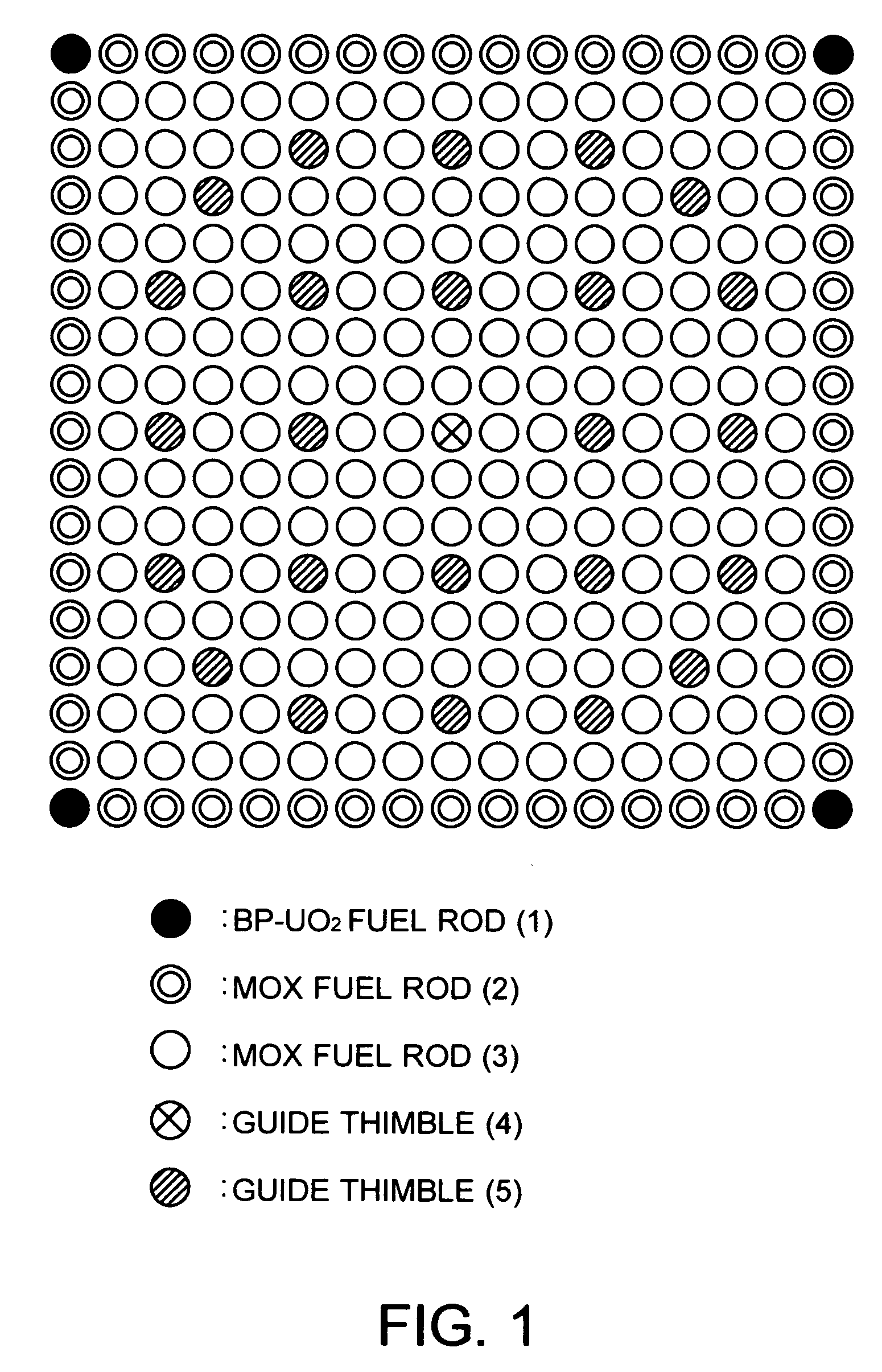
[0024] As this phenomenon exists, in the MOX fuel assembly according to a preferred embodiment of this invention, the thermal neutrons following thereinto from the adjacent UO2 fuel assembly in the reactor core are absorbed by the burnable poison contained UO2 fuel rods arranged in the peripheral zone within the lattice arrangement of the MOX fuel assembly, especially in the four corner locations or in the four corner locations and its adjacent zone, whereby an increase in power of the MOX fuel rods arranged in its adjacence is suppressed. Furthermore, since the first MOX fuel rods having a lower Pu weight are arranged in the outermost zone and its adjacent zone within the lattice arrangement of the MOX fuel assembly, i.e., a zone where the level of the thermal neutron flux flowing thereinto from the adjacent UO2 fuel assembly is high, nuclear fission of Pu by the thermal neutrons flowing into these zones can be controlled in these zones, and as a result the power peaking factor within the assembly can be suppressed as low as or lower than that of the conventional three-stage content distribution type MOX fuel assembly.

Problems solved by technology

However, it was pointed out that this three-stage content distribution type MOX fuel assembly had a drawback of increased manufacturing cost because of the following reasons.
Even this known design uses the MOX fuel rods of two kinds of Pu contents, and does not reach a fundamental solution to the several problems described above.
Therefore, this idea still has a problem of increase in the total manufacturing cost for preparing necessary fuel assemblies.

Method used


Image

  • Mox fuel assembly for pressurized water reactors
  • Mox fuel assembly for pressurized water reactors
  • Mox fuel assembly for pressurized water reactors

Examples


Embodiment Construction

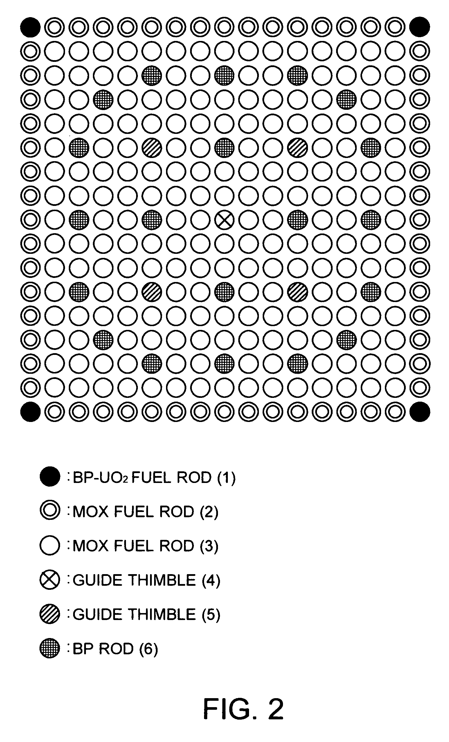
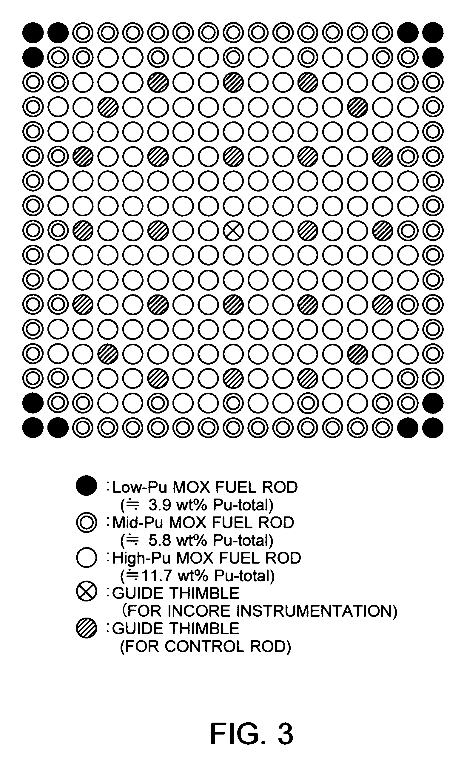
[0035]FIG. 1 shows schematically a lattice arrangement (17×17) of the fuel rods within the MOX fuel assembly according to a first embodiment of this invention. As shown in the figure, the MOX fuel assembly according to this embodiment is for PWRs, and has four (4) BP fuel rods 1, sixty (60) first MOX fuel rods 2, two-hundred (200) second MOX fuel rods 3, one (1) first guide thimble 4 for guiding incore instrumentation that is disposed in the center of the lattice arrangement, and twenty-four (24) second guide thimbles 5 for guiding control rods that are disposed within the lattice arrangement in an almost evenly distributed configuration. Each BP fuel rod 1 is prepared by charging into a cladding tube a plurality of BP pellets each formed by mixing of gadolinium (Gd2O3), as a burnable poison, into uranium dioxide (UO2). The BP fuel rods 1 are arranged in four corner locations of the lattice arrangement. Each first MOX fuel rod 1 is prepared by charging into a cladding tube a plurali...


PUM


Abstract

This invention relates to a MOX fuel assembly for PWRs that enables satisfactorily suppressing a power peaking factor without the necessity of reducing the Pu content per fuel assembly. The MOX fuel assembly has a lattice arrangement in which one or more burnable poison contained UO2 fuel rods and a plurality of MOX fuel rods are disposed in an n-rows by n-columns (n×n) lattice array. The MOX fuel rod consists of at least two kinds of MOX fuel rods including a plurality of first MOX fuel rods and a plurality of second MOX fuel rods. The first MOX fuel rod has a predetermined Pu content and a predetermined Pu weight, and the second MOX fuel rod has substantially the same Pu content as that of the first MOX fuel rod and a different Pu weight from that of the first MOX fuel rod.

Description

TECHNICAL FIELD [0001] This invention relates to a fuel assembly for pressurized water reactors (PWRs), and especially relates to a MOX fuel assembly using MOX fuel rods, i.e., mixed oxide fuel rods containing uranium dioxide and plutonium dioxide. BACKGROUND ART [0002] Conventionally the MOX fuel assembly that has been put in practical use for PWRs is a so-called three-stage content distribution type MOX fuel assembly made up of three kinds of MOX fuel rods that have different Pu contents (wt % of plutonium), respectively, and are arranged, from a center toward a periphery, to form a three-stage (high-medium-low) content distribution in order to suppress a maximum value of the comparative fuel rod power within the assembly (power peaking factor within the assembly). [0003] In this conventional fuel assembly, the MOX fuel rods of the low Pu content and of the medium Pu content are arranged in the peripheral zone within the fuel assembly, and the MOX fuel rods of the high Pu content ...

Claims


Application Information

Patent Timeline
Patent Type & Authority Applications(United States)
IPC IPC(8): G21C1/04G21C3/30
CPCG21C3/326Y02E30/38Y02E30/32G21C3/62Y02E30/30
Inventor HANAYAMA, YASUSHIKAWAMURA, MITSURU
Owner NUCLEAR FUEL INDS
Learn More