
Fuel cell cooling system and method for controlling circulation of cooling liquid in fuel cell

a technology of fuel cell and cooling system, which is applied in the direction of fuel cells, hybrid cells, solid electrolyte fuel cells, etc., can solve the problems of time required before the fuel cell system can be started, the fuel cell system in a vehicle, in particular, cannot be started immediately, etc., to suppress the increase in impurities (ion concentration), and shorten the vehicle startup time

Active Publication Date: 2006-11-30
TOYOTA JIDOSHA KK
View PDF8 Cites 34 Cited by
  • Summary
  • Abstract
  • Description
  • Claims
  • Application Information

AI Technical Summary

Benefits of technology

[0009] In view of the foregoing problems, one object of this invention is to provide a cooling system for a fuel cell which is capable of suppressing an increase in impurities (ion concentration) in a cooling liquid of the fuel cell even after operation of the fuel cell system has stopped.
[0010] Another object of the invention is to provide a cooling system for a fuel cell system in a vehicle, which is capable of shortening the startup time of the vehicle by suppressing an increase in impurities (ion concentration) in a cooling liquid that occurs due to the fuel cell system not being operated for an extended period of time.
[0011] A further object of the invention is to provide a cooling system for a fuel cell system in a vehicle, which is capable of shortening the startup time of the vehicle by suppressing an increase in impurities (ion concentration) in a cooling liquid of the fuel cell by passing the cooling liquid through an impurity-removing device (e.g., an ion filter) and removing the impurities (e.g., ions) from the cooling liquid even after the fuel cell system has stopped operating.

Problems solved by technology

Thus time is required before the fuel cell system can be started.
A fuel cell system in a vehicle, in particular, is unable to be started up immediately because of the time that it takes to remove the ions.
This means that time is required before the vehicle can be driven.

Method used


Image

  • Fuel cell cooling system and method for controlling circulation of cooling liquid in fuel cell
  • Fuel cell cooling system and method for controlling circulation of cooling liquid in fuel cell
  • Fuel cell cooling system and method for controlling circulation of cooling liquid in fuel cell

Examples


Embodiment Construction

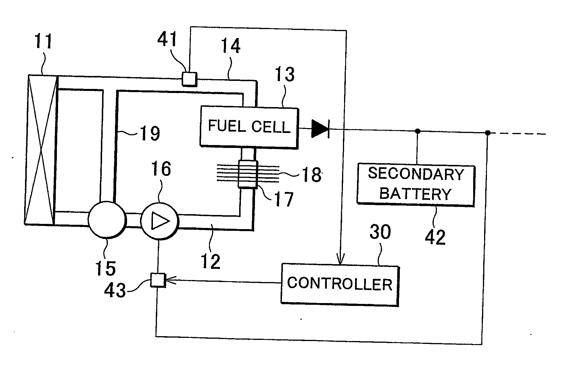
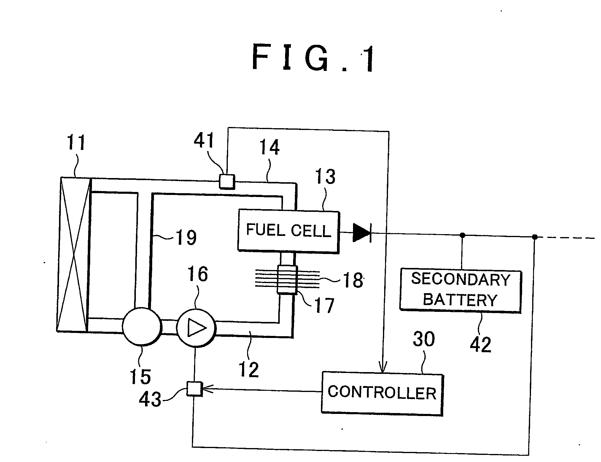
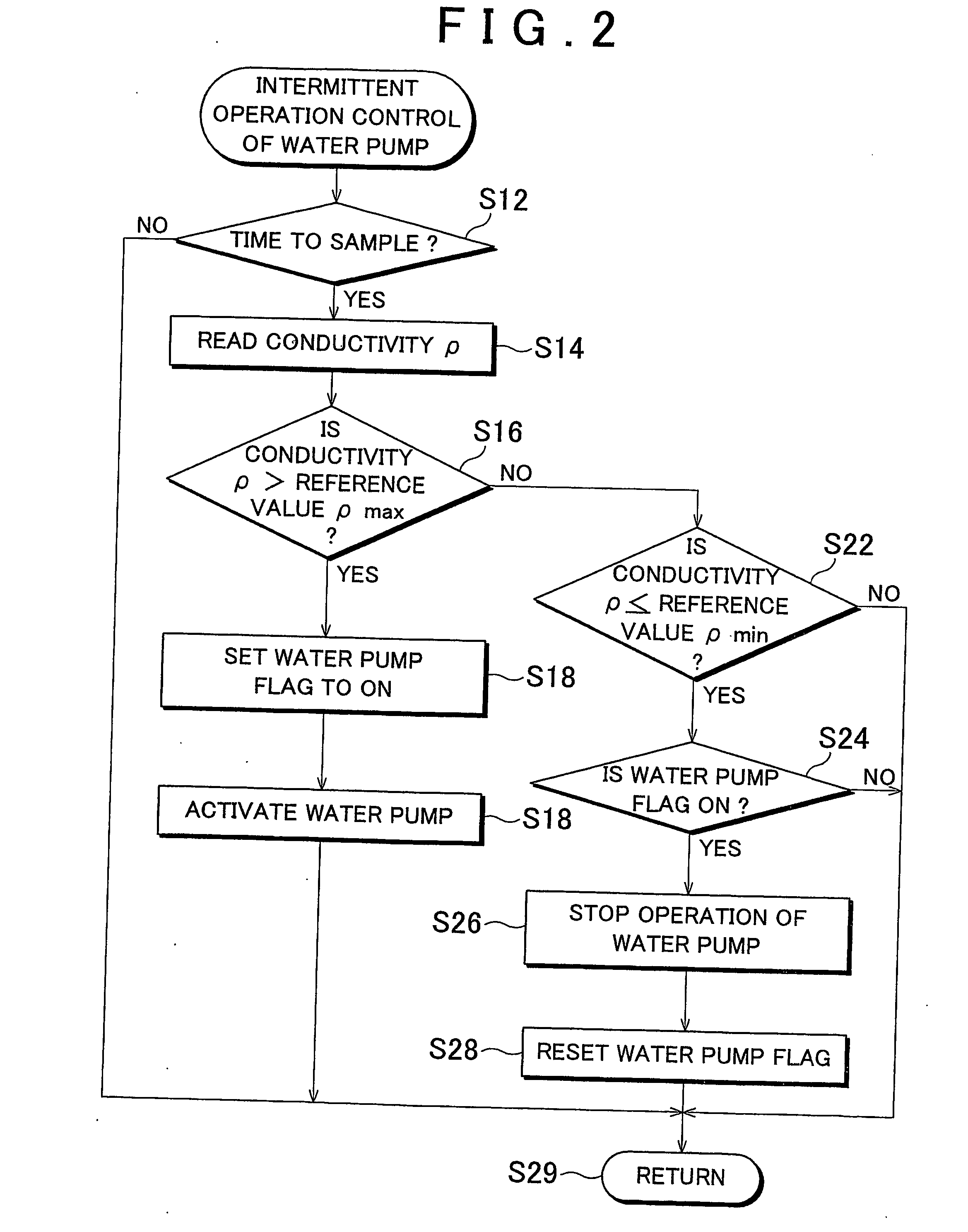
[0060] In the following description and the accompanying drawings, the present invention will be described in more detail in terms of exemplary embodiments. In the exemplary embodiments of this invention, an increase in the concentration of impurities such as ions and particles that have leached into the cooling liquid is suppressed even when a fuel cell is not generating electricity, by passing the cooling liquid through an ion filter which serves as an impurity-removing device. The cooling liquid may be made to flow through the impurity-removing device by being circulated by, for example, a water pump (drive pump) of the fuel cell that is intermittently operated, as in the first through the fifth exemplary embodiments. In this case, the pump can be intermittently operated in response to the state (e.g., quantity) of the impurities in the cooling liquid, e.g., in response to the conductivity or impurity concentration. Alternatively, the cooling liquid of the fuel cell may be made t...


PUM

PropertyMeasurementUnit
temperatureaaaaaaaaaa
impurity detectoraaaaaaaaaa

Abstract

A cooling system for a fuel cell is provided with a cooling apparatus that regulates the temperature of the fuel cell by supplying the fuel cell with a cooling liquid via a cooling liquid passage by means of a water pump; an impurity-removing device which is provided in the cooling liquid passage and which removes impurities from within the cooling liquid; and flow generating means for causing the cooling liquid in the cooling liquid passage to flow through the impurity-removing device when the fuel cell is not operating.

Description

BACKGROUND OF THE INVENTION [0001] 1. Field of the Invention [0002] The invention generally relates to a fuel cell system, and more particularly to the improvement of a cooling system for a fuel cell stack. Also, the invention relates to a method for controlling circulation of a cooling liquid in a fuel cell system. [0003] 2. Description of the Related Art [0004] A fuel cell generates electricity through a chemical reaction. More specifically, a fuel cell is structured such that an electrolyte is sandwiched between an anode and a cathode. Hydrogen or a hydrogen-rich reformate gas is supplied to the anode while oxygen is supplied to the cathode. An electrochemical reaction is then induced which results in the generation of electrical energy. A plurality of these fuel cells are usually combined to form a fuel cell stack. These fuel cells are classified into different types, such as phosphoric-acid fuel cells, solid oxide fuel cells, and polymer electrolyte fuel cells, according to the...

Claims


Application Information

Patent Timeline
Patent Type & Authority Applications(United States)
IPC IPC(8): H01M8/04H01M16/00H01M8/00H01M8/10
CPCH01M8/04029Y02E60/50H01M8/1002H01M8/04044H01M8/1007
Inventor FUJITA, NOBUOKONDO, TOSHIYUKI
Owner TOYOTA JIDOSHA KK
Learn More