
Technique for reducing silicide non-uniformities by adapting a vertical dopant profile

Inactive Publication Date: 2006-11-30
ADVANCED MICRO DEVICES INC
View PDF8 Cites 8 Cited by
  • Summary
  • Abstract
  • Description
  • Claims
  • Application Information

AI Technical Summary

Benefits of technology

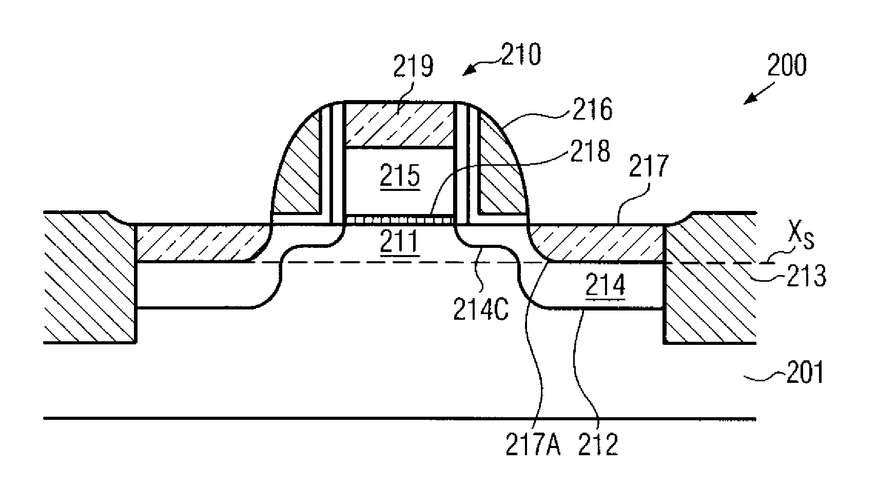
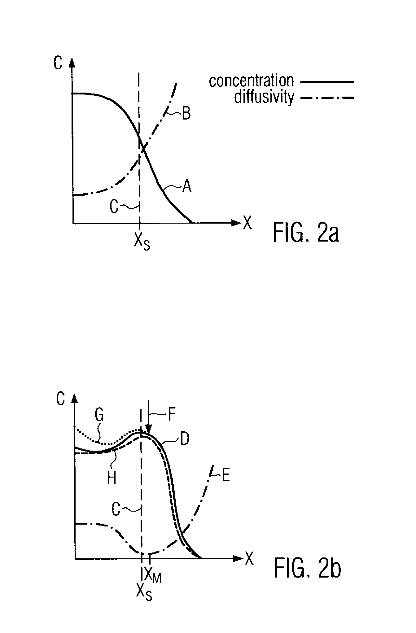
[0019] The present invention is directed to a technique that enables the formation of metal silicide regions in highly doped semiconductor regions containing silicon, wherein the roughness of the metal silicide region may significantly be reduced to provide a more precisely defined interface with the surrounding semiconductor region. For this purpose, a vertical dopant concentration within the silicon-containing semiconductor region may be modified to provide, compared to conventional source and drain regions, an increased dopant concentration at or near a depth at which the interface of the metal silicide region is to be formed. The increased dopant concentration may significantly modify the diffusivity of the metal during the formation of the metal silicide region.

Problems solved by technology

Shrinking the feature sizes, however, entails certain problems that may partially offset the advantages obtained by the reduced feature sizes.
In decreasing the features sizes of these transistor elements, however, the increasing electrical resistance of conductive lines and contact regions, i.e., of regions that connect transistor areas, such as drain and source regions, with the periphery of the transistor element, becomes a dominant issue since the cross-sectional area of these lines and regions decreases with decreasing feature sizes.
While the resistivity of the metal lines may be improved by replacing the commonly used aluminum with, for example, copper and copper alloys, process engineers are confronted with a challenging task when an improvement in the electrical characteristics of silicon-containing semiconductor lines and semiconductor contact regions is required.
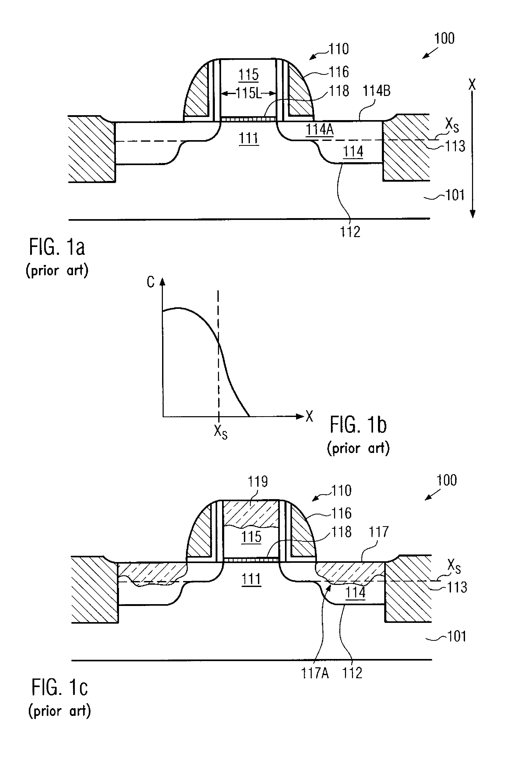
Moreover, with the continuous drive for scaling semiconductor devices, non-uniformities of the metal silicide regions 117 may negatively affect the performance of future device generations having even more tightly set process tolerances.

Method used


Image

  • Technique for reducing silicide non-uniformities by adapting a vertical dopant profile
  • Technique for reducing silicide non-uniformities by adapting a vertical dopant profile
  • Technique for reducing silicide non-uniformities by adapting a vertical dopant profile

Examples


Embodiment Construction

[0031] Illustrative embodiments of the invention are described below. In the interest of clarity, not all features of an actual implementation are described in this specification. It will of course be appreciated that in the development of any such actual embodiment, numerous implementation-specific decisions must be made to achieve the developers' specific goals, such as compliance with system-related and business-related constraints, which will vary from one implementation to another. Moreover, it will be appreciated that such a development effort might be complex and time-consuming, but would nevertheless be a routine undertaking for those of ordinary skill in the art having the benefit of this disclosure.

[0032] The present invention will now be described with reference to the attached figures. Various structures, systems and devices are schematically depicted in the drawings for purposes of explanation only and so as to not obscure the present invention with details that are we...


PUM


Abstract

By modifying the vertical dopant concentration in deep drain and source regions, the reaction behavior during the formation of metal silicide regions may be controlled. For this purpose, an increased dopant concentration is formed around a target depth for the metal silicide interface, thereby reducing the reaction speeds and thus improving the uniformity of the resulting metal silicide interface.

Description

BACKGROUND OF THE INVENTION [0001] 1. Field of the Invention [0002] Generally, the present invention relates to the field of fabrication of integrated circuits, and, more particularly, to semiconductor devices having metal-silicide portions on semiconductor regions to reduce the resistance of the semiconductor regions. [0003] 2. Description of the Related Art [0004] In modern ultra-high density integrated circuits, device features are steadily decreasing to enhance device performance and functionality. Shrinking the feature sizes, however, entails certain problems that may partially offset the advantages obtained by the reduced feature sizes. Generally, reducing the feature sizes of, for example, a transistor element may lead to a decreased channel resistance in the transistor element and thus result in a higher drive current capability and enhanced switching speed of the transistor. In decreasing the features sizes of these transistor elements, however, the increasing electrical re...

Claims


Application Information

Patent Timeline
IPC IPC(8): H01L21/04
CPCH01L21/26513H01L21/28518H01L21/823814H01L29/66628H01L29/66507H01L29/6656H01L29/6659H01L29/4933
Inventor WIRBELEIT, FRANKBROWN, DAVIDPRESS, PATRICK
Owner ADVANCED MICRO DEVICES INC
Learn More