Wireless communication system, wireless relay unit and wireless terminal constituting the wireless communication system, and wireless communication method

a wireless communication and wireless communication technology, applied in the field of wireless communication systems, wireless relay units and wireless terminals constituting the wireless communication system, can solve the problems of difficult effective utilization of communication bands and complicated timing adjustment of wireless transmissions, and achieve simplified timing adjustment methods for wireless transmissions, effective use of communication bands, and suppression of hidden terminal problems

Inactive Publication Date: 2006-11-30
HITACHI LTD
View PDF5 Cites 63 Cited by
  • Summary
  • Abstract
  • Description
  • Claims
  • Application Information

AI Technical Summary

Benefits of technology

[0060] According to the aforementioned aspects of the present invention, a wireless relay unit is allowed to transmit a transmission clearance signal which gives clearance for transmission to a particular wireless terminal, unlike the conventional second method in which a wireless terminal is required to transmit an RTS signal. Therefore, it is possible to suppress occurrence of hidden terminal problem, and further, timing adjustment method for wireless transmission is simplified as well as achieving an effective use of communication band.

Problems solved by technology

The conventional first method is a simple way for adjusting timing in a wireless transmission, but there is a problem that contention may occur due to a hidden terminal problem or the like.
However, timing adjustment in the wireless transmission is complicated.
Therefore, there are problems such that it takes time to perform the data transmission, and thus effective utilization of communication band is hardly achieved.

Method used


Image

  • Wireless communication system, wireless relay unit and wireless terminal constituting the wireless communication system, and wireless communication method
  • Wireless communication system, wireless relay unit and wireless terminal constituting the wireless communication system, and wireless communication method
  • Wireless communication system, wireless relay unit and wireless terminal constituting the wireless communication system, and wireless communication method

Examples


first embodiment

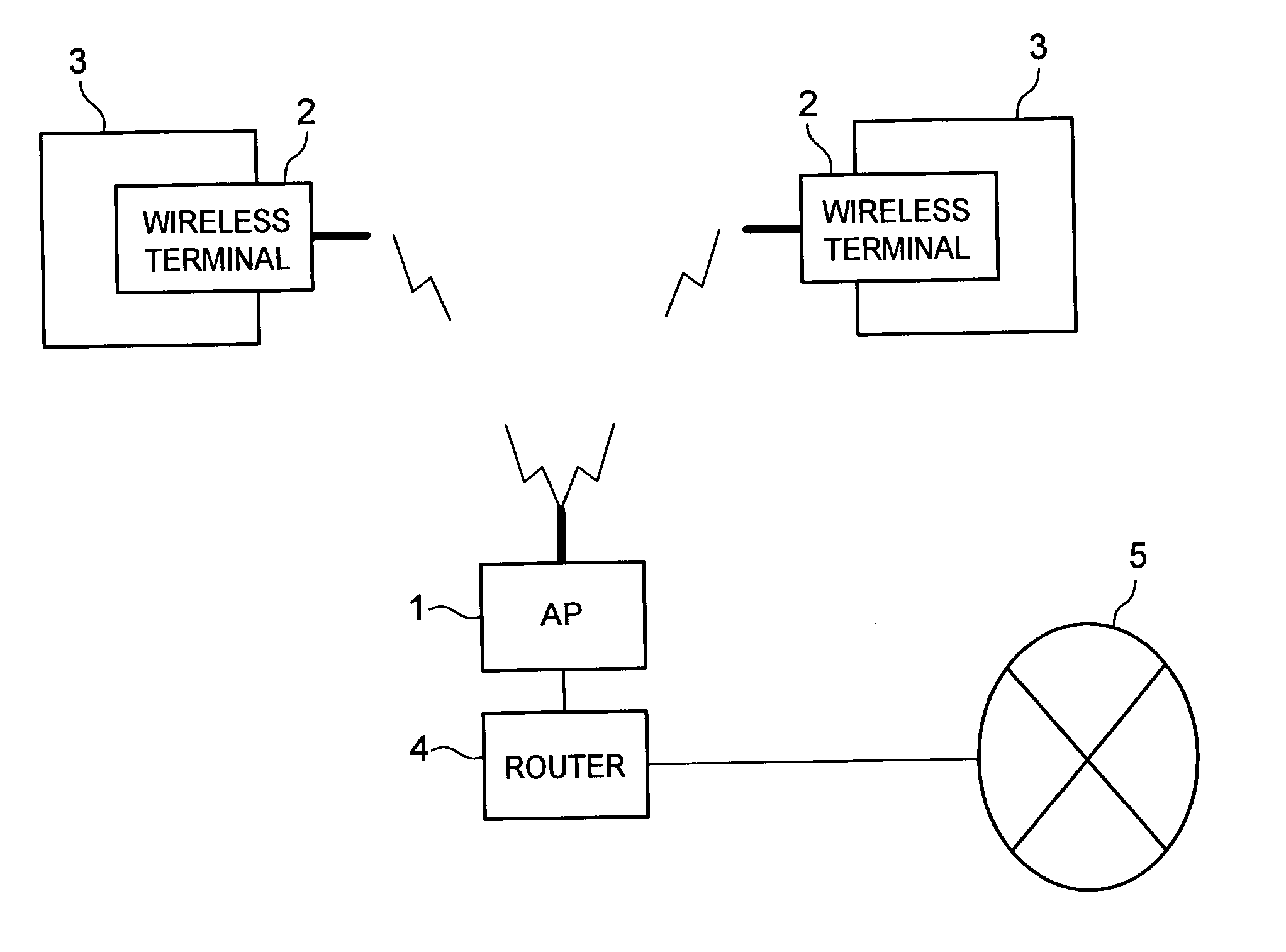
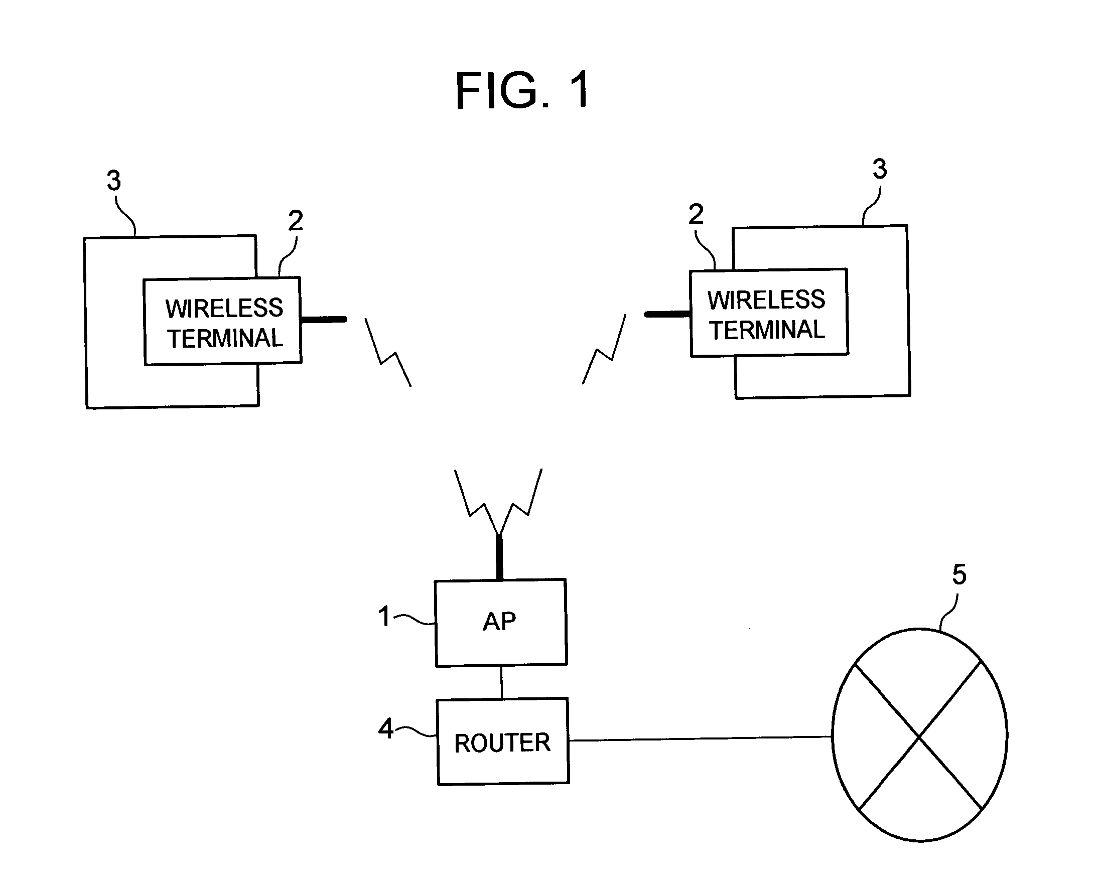
[0081] Firstly, referring to FIG. 1 to FIG. 7, the wireless LAN system according to the present invention will be explained.

[0082] As shown in FIG. 1, the wireless LAN system according to the present embodiment is provided with a wireless LAN card 2 being a wireless terminal, a computer 3 on which the wireless LAN card is mounted, an access point (AP) 1 being a relay unit for each wireless terminal, and router 4 to establish wired connection with a public network 5 such as the Internet.

[0083] Each wireless terminal transmits data received from the computer 3 to AP 1 with a designation of a wireless terminal as a data-sending destination. Therefore, it is possible to transmit the data to any one of the terminals which are connected to the aforementioned wireless LAN system.

[0084] The computer 3 on which the wireless LAN card 2 is mounted, is provided with a memory such as ROM and RAM, CPU to execute a program stored in this memory, man-machine interface, and a card slot to place th...

second embodiment

[0120] As a countermeasure against the problem above, the second embodiment will be explained with reference to FIG. 9 and FIG. 10.

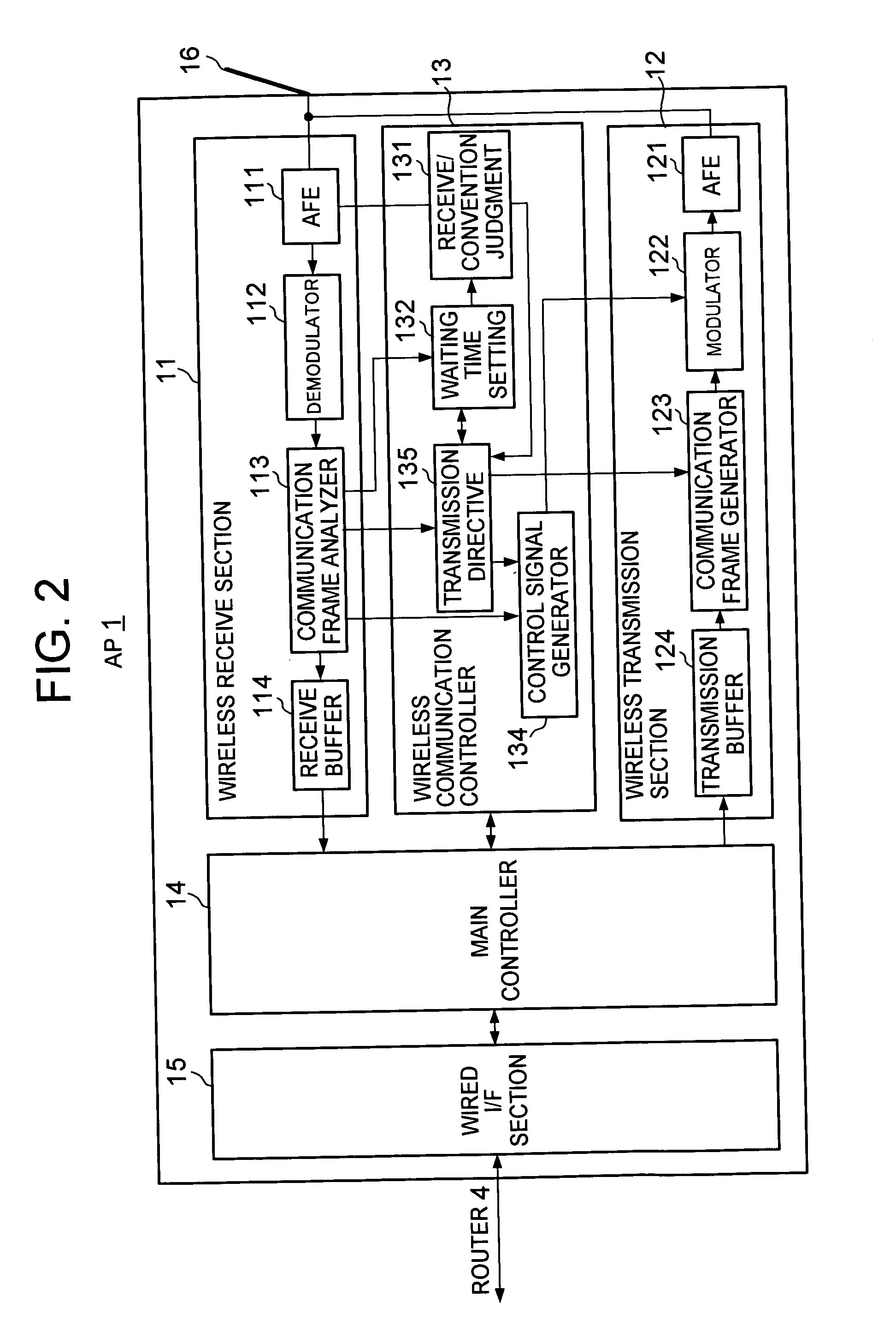
[0121] The configurations of AP 1 and wireless terminal 2 in the wireless communication system according to the second embodiment are basically the same as those in the first embodiment. However, it is different from the first embodiment in the point that additional operations are provided on each functional part of the AP 1. Specifically, in the first embodiment, immediately after detection of transmission error (S110), the AP 1 waits for a completion of receiving the wireless signal (S121). On the other hand, in the present embodiment, as shown in the flowchart of FIG. 10, after detection of the transmission error (S110), the AP 1 starts transmitting a dummy signal (S120), and at the time of completion of receiving the wireless signal (S121), transmission of the dummy signal is stopped (S120a).

[0122] The control signal generator 134 of the AP 1 genera...

third embodiment

[0124] Next, with reference to FIG. 11 to FIG. 14, wireless LAN system will be explained.

[0125] The wireless LAN may handle signals sent out at irregular intervals, like a general data signal, but also handle signals sent out at a constant frequency such as audio signal or image signal originally, when an audio signal being an analogue signal is transmitted via LAN, the audio is sampled at a constant frequency, and is subjected to high-efficient encoding. Then, for example, an audio signal corresponding to 20 ms is sent out in a form of an audio signal corresponding to a few ms, that is, in the wireless LAN, audio signals corresponding to a few ms are transmitted in 20 ms period. Therefore, once transmission and receiving of the audio signals are started between the AP and a wireless terminal, the AP is allowed to know in advance an address of this wireless terminal, a clock time when this wireless terminal sends the audio signal, and duration, which are data items necessary for ge...


PUM


Abstract

The present invention is to provide a wireless LAN system which achieves a relatively effective use of communication band, while suppressing occurrence of hidden terminal problems.
When wireless terminal A and wireless terminal B respectively transmit signals (T123, T133), and Access Point (AP) in the wireless LAN system recognizes occurrence of contention, if AP successfully recognizes an address of sending source of this signal and a duration of this signal as a result of analyzing any signal from the wireless terminal A, AP transmits a CTS signal which gives a clearance for transmission to the wireless terminal A which is the source of sending the signal (T113). The wireless terminal A which is given the clearance for transmission by the CTS signal, resends a signal identical to the one previously sent (T127), whereas the wireless terminal B which is not given the clearance for transmission by the CTS signal withholds a signal transmission during the duration indicated by the CTS signal.

Description

TECHNICAL FIELD [0001] The present invention relates to a wireless communication system, such as wireless LAN, including a wireless relay unit referred to as “access point”, and a wireless terminal which establishes connection with another terminal via this wireless relay unit, and also relates to the wireless relay unit and the wireless terminal constituting this system, and a wireless communication method. BACKGROUND OF THE INVENTION [0002] As generally known, in wireless LAN, a wireless relay unit referred to as “access point (hereinafter, abbreviated as “AP”)” and multiple wireless terminals are connected via wireless communication. Since in this wireless LAN, those multiple wireless terminals and the AP (hereinafter, each of these elements will be simply referred to as a “device”) establish communication sharing a single space, a wireless signal can be transmitted from only one of those devices at a time. Therefore, it is necessary to adjust timing when transmission is performe...

Claims


Application Information

Patent Timeline
Patent Type & Authority Applications(United States)
IPC IPC(8): H04N7/18H04N7/16H04W16/02H04W72/04H04W72/12H04W74/04H04W74/08H04W84/12H04W88/04H04W88/08
CPCH04W72/12H04W88/04H04W84/12H04W74/0808
Inventor TAKIZAWA, MASAAKISUZUKI, TSUTOMU
Owner HITACHI LTD
Why Eureka
Try Eureka