Automated microtome blade changer

a technology of automatic change and microtome, which is applied in the direction of metal sawing devices, metal sawing apparatus, manufacturing tools, etc., can solve the problems of not providing safety features, not revealing a method or apparatus for the change of individual blades, and reducing the chance of being cut accidentally. , the effect of reducing the chance of being cu

Inactive Publication Date: 2006-12-07
VENTANA MEDICAL SYST INC
View PDF21 Cites 25 Cited by
  • Summary
  • Abstract
  • Description
  • Claims
  • Application Information

AI Technical Summary

Benefits of technology

[0016] It is an object of the present invention to provide a fully automated blade changer for the histopathology laboratory that reduces and hopefully eliminates the chances of being cut accidentally during routine laboratory operations with the microtome blades.
[0017] It is another object of the present invention to provide a new blade cartridge that, in cooperation with a microcontroller in the blade changer, can track blade useage and signal the user when blades are running low.

Problems solved by technology

This exposed the user to the edges of the blade, and of course the potential of serious injury.
The '330 patent does not disclose a method or apparatus for the changing of individual blades, or provide safety features for the changing of the blade.

Method used


Image

  • Automated microtome blade changer
  • Automated microtome blade changer
  • Automated microtome blade changer

Examples


first embodiment

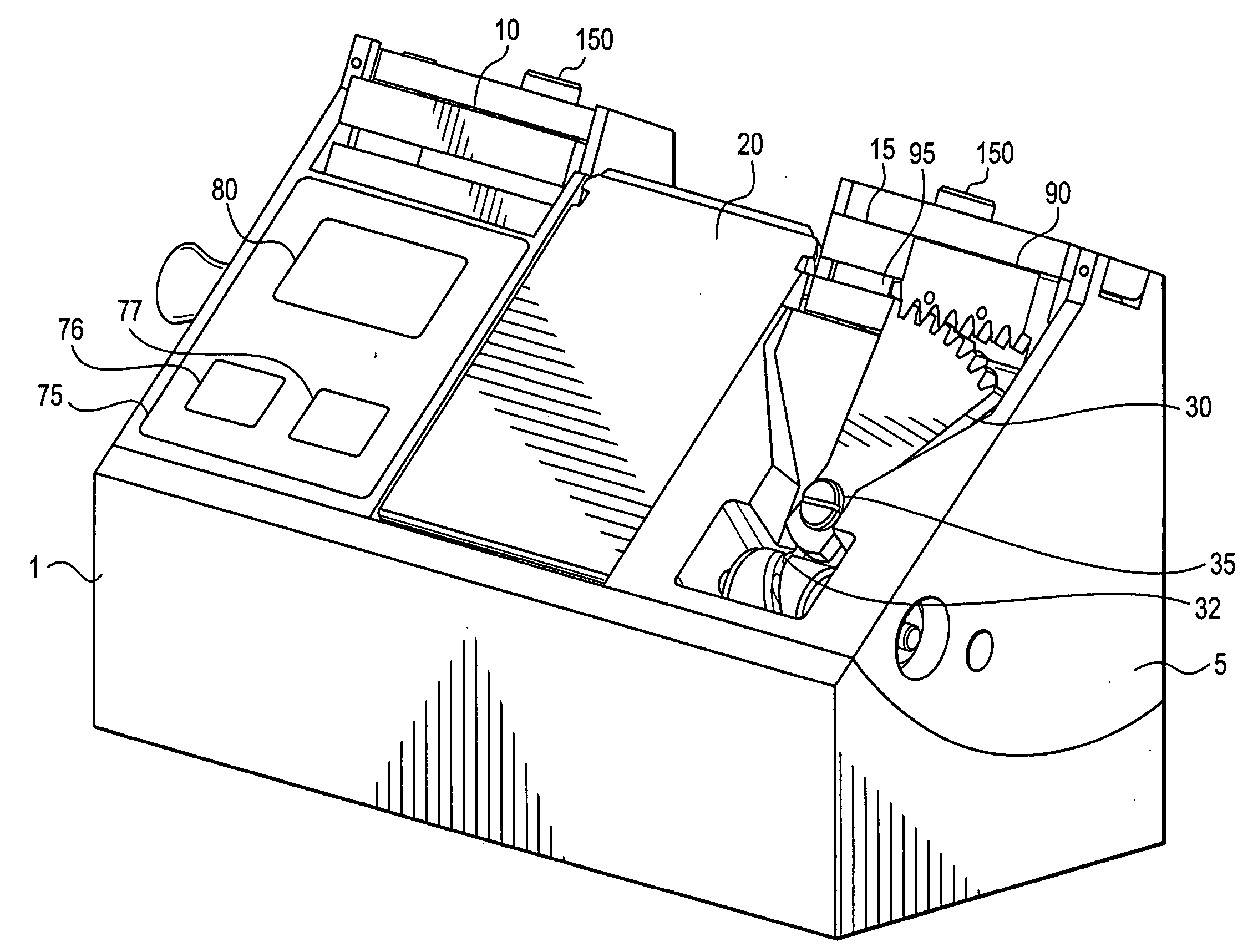
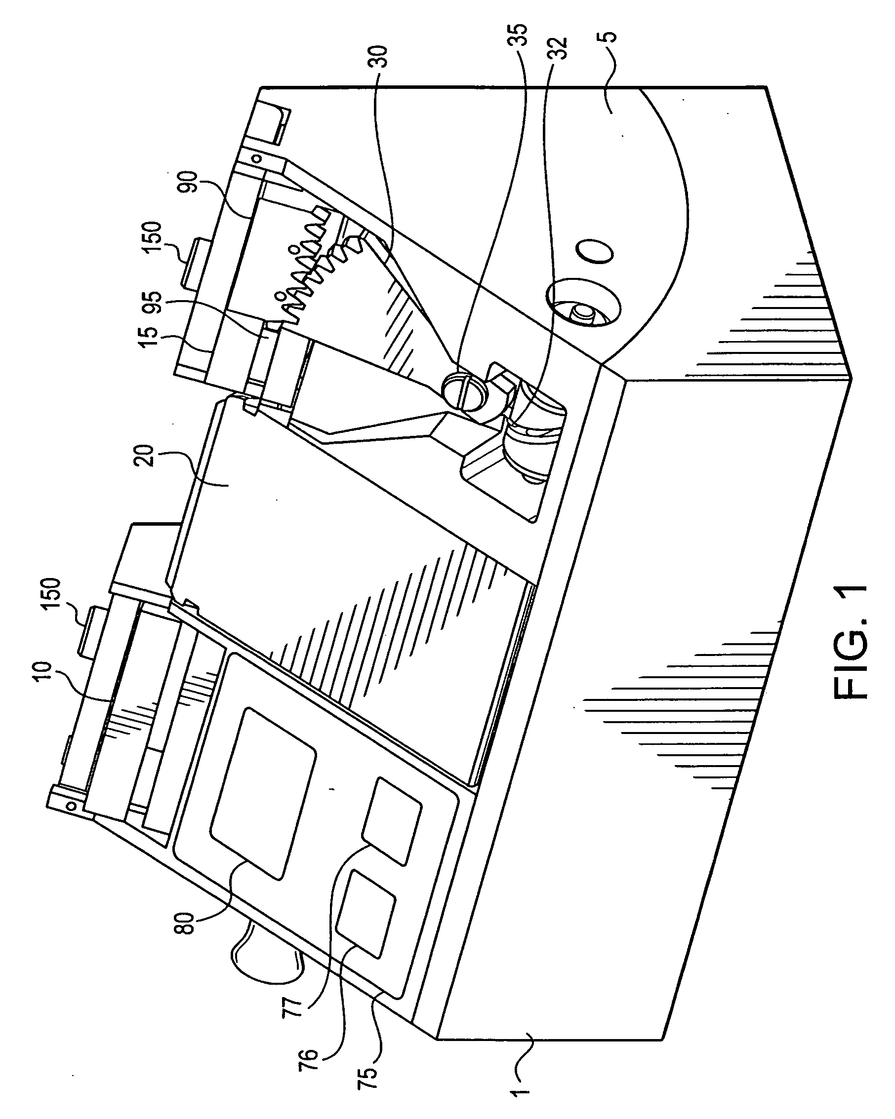
[0031] the blade changer comprises lower and upper stage bodies 1, 5, respectively. With reference to FIG. 1 the microtome blade cartridges are removably located within the upper stage body 5. The lower stage body is adaptable to a wide variety of rotary microtomes, and serves as the common interface mounting for the upper stage. The disposable blade cartridges 10, 15 are adapted to lock into the upper stage body 5 so as to provide an element of safety. The cartridges are described more fully below and in FIGS. 3-5. They are releasable only when the individual blades are fully secured within the body of the cartridge. This “interlock” function can be attained in many ways, however a preferred embodiment includes an on-board microcontroller which monitors the state of operation of the blade changer. When the controller's logic functions determine that no blade edges are exposed, then the clamping plate and / or the cartridges may be released. The interlock function is more fully descri...

second embodiment

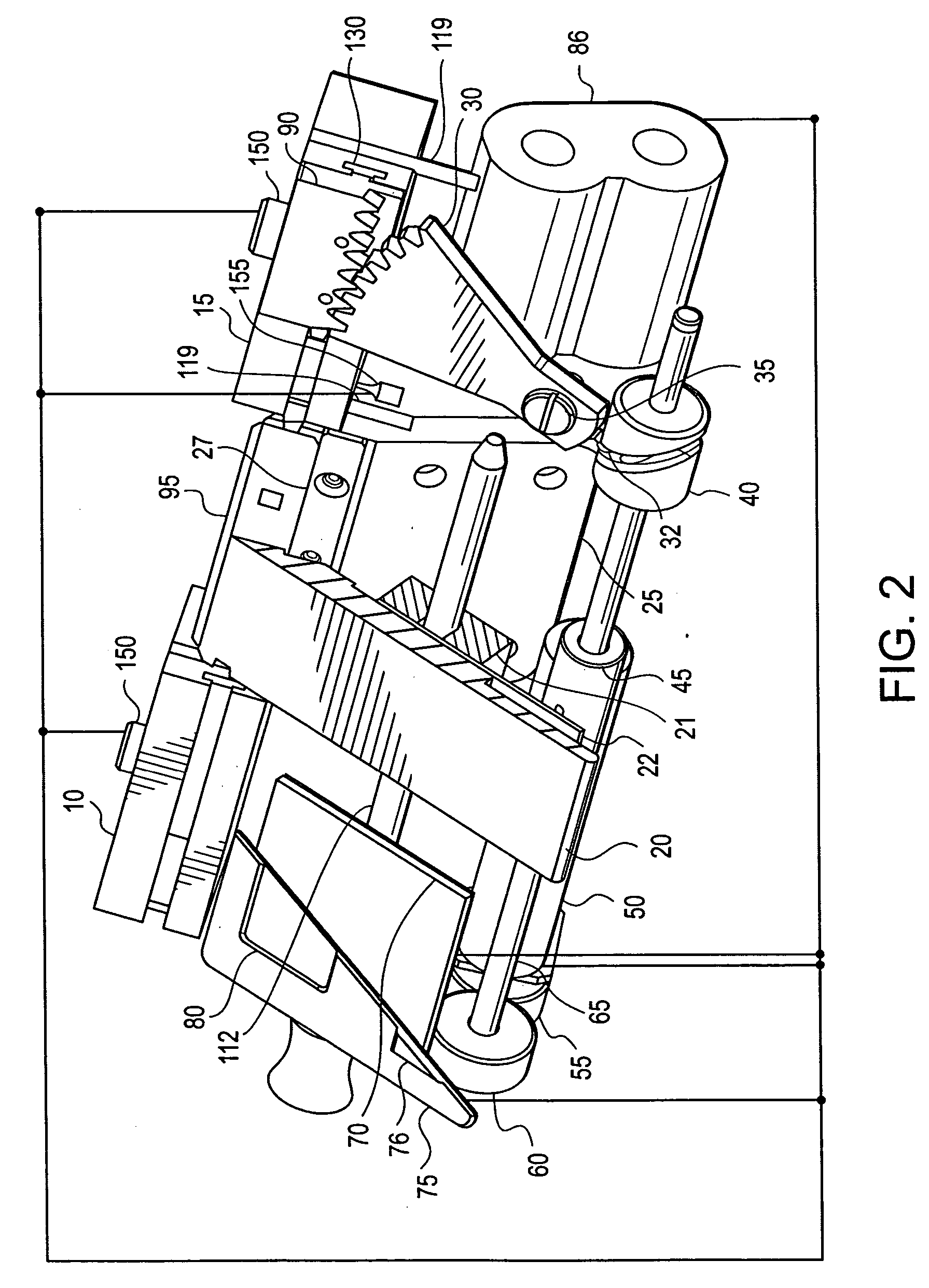
[0039] Again with reference to FIG. 3, supply cartridge 15 has a dispensing tab 90 integral with the cartridge and adapted for engaging each new blade 95. Downward protrusion 92 engages a slot or opening in each new blade. The downward protrusion may be a metal tab, a plastic hook or similar equivalent article. The main design limitation is that it reliably contact only one blade at a time. Downward protrusion 92 may be located anywhere on dispensing tab 90 so long as it functions to urge a single blade out of the cartridge for each cycle of the loading segment 30. In the preferred embodiment shown in FIG. 3, the protrusion is forward mounted on the blade side of dispensing tab 90. the dispensing tab is shown in FIGS. 7-8. The primary feature is that dispensing tab shown (290) is designed with a slot or cutout for engaging shuttle tab 231. It does not have the teeth necessary for engaging the loading segment 30, which is not present in this embodiment.

[0040] The safety interlock fea...


PUM

PropertyMeasurementUnit
Semiconductoraaaaaaaaaa
poweraaaaaaaaaa
pressureaaaaaaaaaa

Abstract

An automated rotary microtome blade changing apparatus, comprising an upper stage being adapted to releasably engage a supply cartridge and a waste cartridge, the upper stage having a loading segment adapted to engage and move blades contained within the supply cartridge into a cutting position; clamping means for releasably holding the blades in place for cutting operations; power means for driving the movement of blades and clamping mechanisms; and electronic control means for integrating all of the functions of the apparatus.

Description

RELATED APPLICATIONS [0001] This application is a continuation-in-part of commonly assigned U.S. Ser. No. 09 / 562,270, filed Apr. 29, 2000.BACKGROUND [0002] 1. Field of the Invention [0003] The present invention is directed to apparatus for use in preparing tissue sections for use in diagnostic histopathology and, more particularly, to an apparatus that automatically changes the blades of a microtome without exposure of the user to the cutting edges of the blades. [0004] 2. Description of Related Art [0005] Microtomes have been used for many years to meet the exacting requirements necessary for thin sectioning of paraffin-embedded tissue. Essentially, microtomes are holders for razor-sharp metal blades, against which a block of paraffin-embedded tissue is moved in an up-and-down motion. Concurrently, either the tissue block is advanced against the blade, or vice versa, so that with each up or down stroke, a thin slice or “section” of tissue is cut from the block. The blades are highl...

Claims


Application Information

Patent Timeline
Patent Type & Authority Applications(United States)
IPC IPC(8): B26D5/20G01N1/06
CPCY10S83/954G01N1/06Y10T83/6536Y10T83/6492Y10T83/18Y10T83/9457B26D7/2614
Inventor HENDRICK, KENDALL B.MCDANIEL, DARINHOLUBEC, MIROSLAVRICHARDS, WILLIAMRIZZO, VINCENT
Owner VENTANA MEDICAL SYST INC
Why Eureka
Try Eureka