High Power Cold Cathode Tubular Fluorescent Lamp

a fluorescent lamp and tubular technology, applied in the field of cold cathode fluorescent lamps, can solve the problems of difficult implementation of dimming hot cathode fluorescent lamps, short operating life, short on/off switching lifetime, etc., and achieve the effect of increasing the length

Inactive Publication Date: 2006-12-07
TBT ASSET MANAGEMENT INT
View PDF24 Cites 17 Cited by
  • Summary
  • Abstract
  • Description
  • Claims
  • Application Information

AI Technical Summary

Benefits of technology

[0009] In one embodiment of such CCFL device, such device comprises at least two CCFLs: at least one high color temperature light tube and at least one low color temperature light tube, or at least one low color temperature light tube and at least one green-blue color light tube. By using one or more drivers to control power supplied to the CCFLs to change the relative light intensities of the light emitted by the high and low color temperature CCFL tubes, or the low color temperature light tube and the green-blue color light tubes to obtain different color temperature light, it is possible to design the device as a light color temperature adjustable lamp and / or a color temperature adjustable and dimmable lamp.
[0010] In addition to using the above CCFL device arrangement for lighting applications as a replacement for the hot cathode FL, it is also possible to design a CCFL device that generates multi-color lighting for various purposes such as entertainment. For this purpose, two or more CCFLs may be used. A driver circuit converts input electric power to an AC output in the range of about 5-400 volts and at a frequency in the range of about 1 kc-800 kc. At least one high voltage transformer responds to said AC output to cause suitable voltage(s) to be supplied to each of the CCFLs to cause the CCFLs to supply light. In one embodiment, a plurality of CCFL lamp units are used, each equipped with its high voltage transformer(s) that supplies a suitable voltage to the CCFL(s) of such unit. Hence, one or more driver circuits applying AC outputs to the two or more CCFL lamp units may apply AC outputs that are different from one another, so that the two or more CCFL units are individually controlled to emit light of the same or different intensities.
[0011] In one embodiment, a single driver is used to control the electric power supplied to more than one CCFL unit, where each unit has it own high voltage transformer(s). In an alternative embodiment, multiple drivers are used, one for each unit, where each unit has it own high voltage transformer(s). The CCFLs may be enclosed within the same light transmission tube, or its own light transmission tube. The CCFLs in the units may emit light of the same color for high intensity applications, or different color light for entertainment purposes.
[0012] Since the light power emitted by a CCFL is proportional to its length, it is desirable to employs CCFLs that have longer lengths. Preferably, the CCFLs used in the embodiments are not straight to increase their length, while being able to fit the resulting lamp device within practical dimensions. The hot cathode FL usually is about two feet in length. The CCFLs in the shape of a straight line of only two feet may not be able to emit adequate light for high power applications. Preferably the CCFLs may be U or H shaped, or another shape that is not a straight line to increase their length, while being able to fit the resulting lamp device within practical dimensions, such as a space of only two feet in length.

Problems solved by technology

However, it has a short operating lifetime, very short ON / OFF switching lifetime, and dimming the hot cathode FL is difficult to implement, especially when dimming through a wide range of light intensities or when linear dimming is desired.
It is also, difficult to control and change the color of light emitted by the hot cathode FL or to change its color temperature.
However, the current state of CCFL technology is still unable to make a high power tubular fluorescent lamp for replacement of the current high power hot cathode FL.
However, the length of the CCFL tube in the lamp is short and the efficiency is low.
At the same time, it needs a high voltage for the CCFL lamp driving, and there may be safety concerns when using such lamp.

Method used


Image

  • High Power Cold Cathode Tubular Fluorescent Lamp
  • High Power Cold Cathode Tubular Fluorescent Lamp
  • High Power Cold Cathode Tubular Fluorescent Lamp

Examples


Embodiment Construction

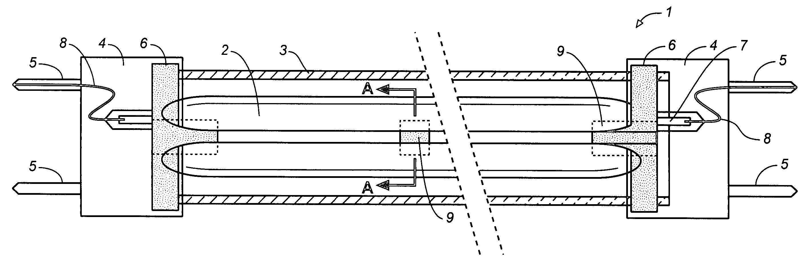
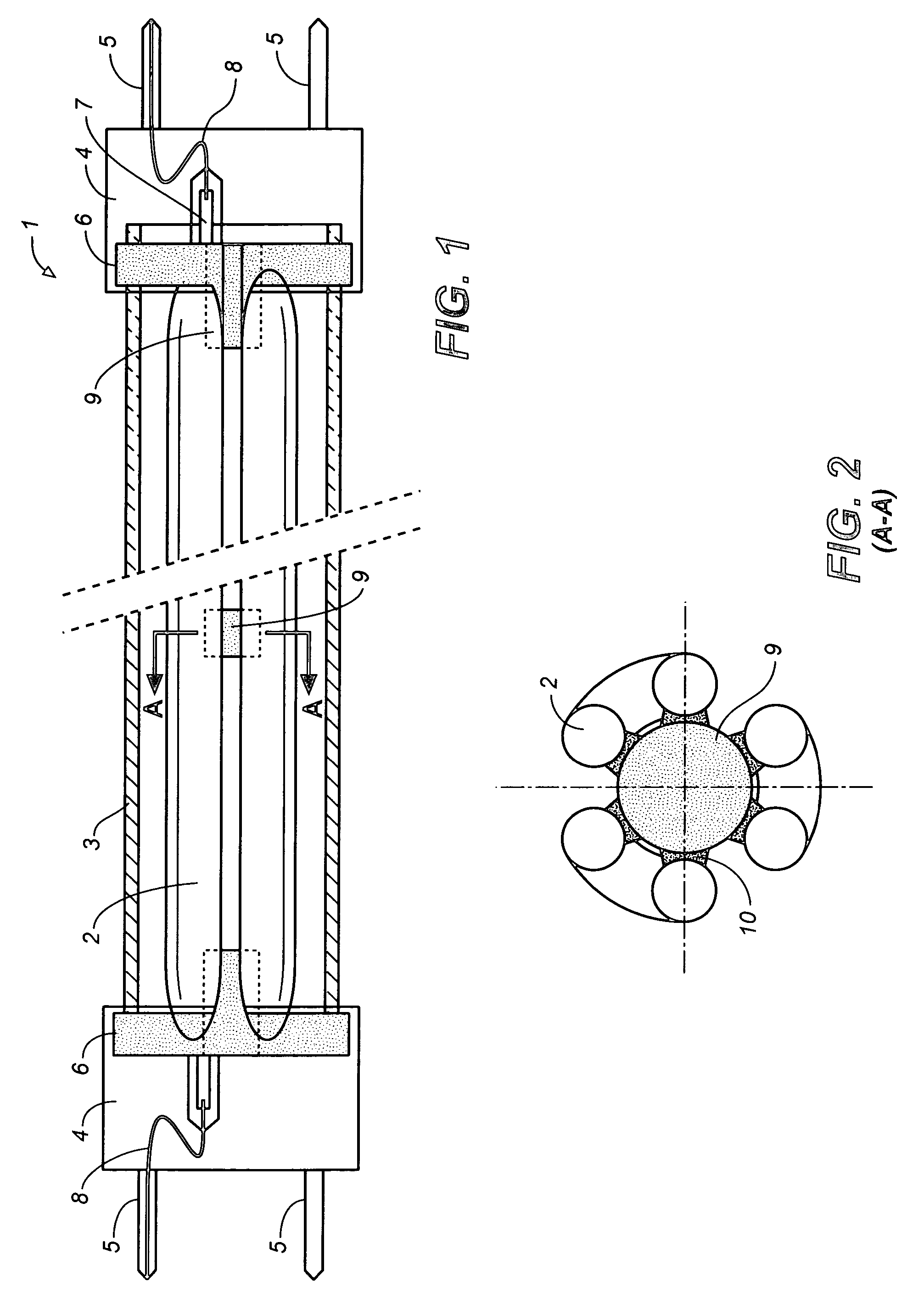
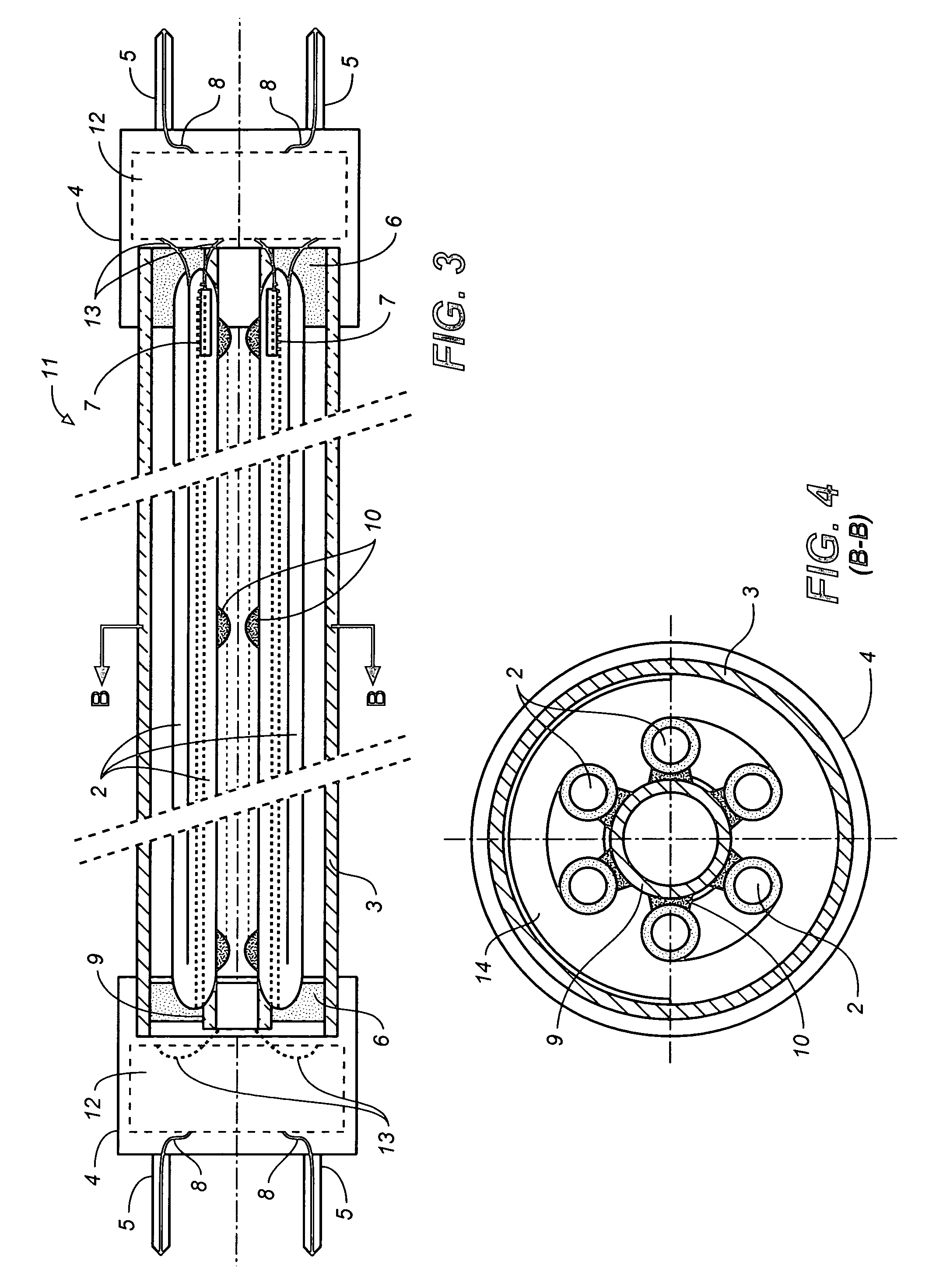
[0038] The present invention provides a high power, high efficiency and high output luminous flux CCFL tubular FL, which can replace the existing high power tubular hot cathode FL. In one embodiment, it comprises at least one “U” shape, multi-“U” shape CCFL or at least one “(n+½)U” shape CCFL tube. The case of a “(n+½)U” shape CCFL tube, where n=1 is illustrated in FIG. 20. Thus, if one side of the U-shape has a length of two feet, then the total length of the U-shaped CCFL tube is 4 feet. In order to further increase its length, one end of the U-shaped CCFL tube may be further extended but bent in a direction to form a serpentine shape illustrated in FIG. 20, which comprises a U-shape plus one half of a U-shape. Thus, if a two feet long CCFL emits light at 6 watts, then a U-shaped CCFL tube whose two prongs are two feet long each will emit light at 12 watts. By adopting the shape of the CCFL in FIG. 20, the length of the CCFL is increased by another two feet, so that the CCFL will ...


PUM


Abstract

A high power tubular CCFL device comprises at least one CCFL; and a light transmission tube having two ends, where the at least one CCFL is at a fixed location inside the light transmission tube. At least two fixtures are used, one fixture at each of the two ends of the light transmission tube. At least two connectors are used, one connector at each of the two ends of the light transmission tube for connection to input electric power. Preferably a portion of a driver (which preferably includes at least one high voltage transformer) is employed in the fixture. The fixture connects the light transmission tube, the CCFL(s) and the connector. When input electric power is supplied to the connector, the portion of the driver (e.g. at least one high voltage transformer) will cause suitable voltage to be supplied to cause the CCFL to supply light. The above described CCFL device is suitable for replacing the hot cathode. To design a CCFL device that generates multi-color lighting for various purposes such as entertainment, two or more CCFLs may be used. A driver circuit converts input electric power to an AC output in the range of about 5-400 volts and at a frequency in the range of about 1 kc-800 kc. At least one high voltage transformer responds to said AC output to cause suitable voltage(s) to be supplied to each of the CCFLs to cause the CCFLs to supply light. In one embodiment, a plurality of CCFL lamp units are used, each equipped with its own driver control circuit that supplies a suitable voltage to the CCFL of such unit. Hence, the driver circuits applying AC outputs to the two or more CCFL lamp units may apply AC outputs that are different from one another, so that the two or more CCFL units are individually controlled to emit light of the same or different intensities.

Description

CLAIM OF FOREIGN PRIORITY [0001] This application claims the benefit of the following foreign applications: Chinese Application No. 200520102770.3, filed Jun. 6, 2005; Chinese Application No. 200520013346.1, filed Jul. 18, 2005; Chinese Application No. 200520015008.1, filed Sep. 19, 2005; Chinese Application No. 200520117017.1, filed Dec. 2, 2005; and Chinese Application No. 200520134334.4, filed Dec. 26, 2005. BACKGROUND OF THE INVENTION [0002] 1. Field of the Invention [0003] The present invention relates generally to a cold cathode fluorescent lamp and more particularly, to a high power tubular cold cathode fluorescent lamp for lighting. [0004] 2. Description of the Prior Art [0005] The existing high power tubular fluorescent lamps (FL), e.g., T12, T10, T8, T5 and T4 FL etc. are the hot cathode FL. It has been used for lighting beginning around 1940, and is widely used in the world now. It has the advantages of high efficiency, low cost and able to generate different color light....

Claims


Application Information

Patent Timeline
Patent Type & Authority Applications(United States)
IPC IPC(8): H01K1/62
CPCH01J5/48H01J5/54H01J61/56H01J61/34H01J61/325
Inventor GE, SHICHAO
Owner TBT ASSET MANAGEMENT INT
Why Eureka
Try Eureka