Carbon nanotube-based electronic switch

a carbon nanotube and electronic switch technology, applied in the field of electronic switching, can solve the problems of limiting the overall miniaturization of computing devices, high insertion losses, and certain critical components that have not progressed as quickly, and achieves low insertion losses, low switching power, and high immunity to electronic switching noise.

Inactive Publication Date: 2006-12-07
CABOT MICROELECTRONICS CORP
View PDF22 Cites 11 Cited by
  • Summary
  • Abstract
  • Description
  • Claims
  • Application Information

AI Technical Summary

Benefits of technology

[0011] Some of the benefits attainable by the exemplary embodiment of the switch described herein are that it has low insertion loss, high immunity to electronic switching noise, and has low switching power. Due to the extremely s...

Problems solved by technology

However, certain critical components have not progressed as rapidly with respect to miniaturization, and the effects of this lag are beginning to limit the overall miniaturization of computing devices.
There are a number of difficulties associated with the production and use of solid-state switches such as those discussed above.
Drawbacks include high insertion losses, high contact resistance, high switching capacitance, signal and gate cross-coupling, high-frequency electronic ...

Method used


Image

  • Carbon nanotube-based electronic switch
  • Carbon nanotube-based electronic switch
  • Carbon nanotube-based electronic switch

Examples


Embodiment Construction

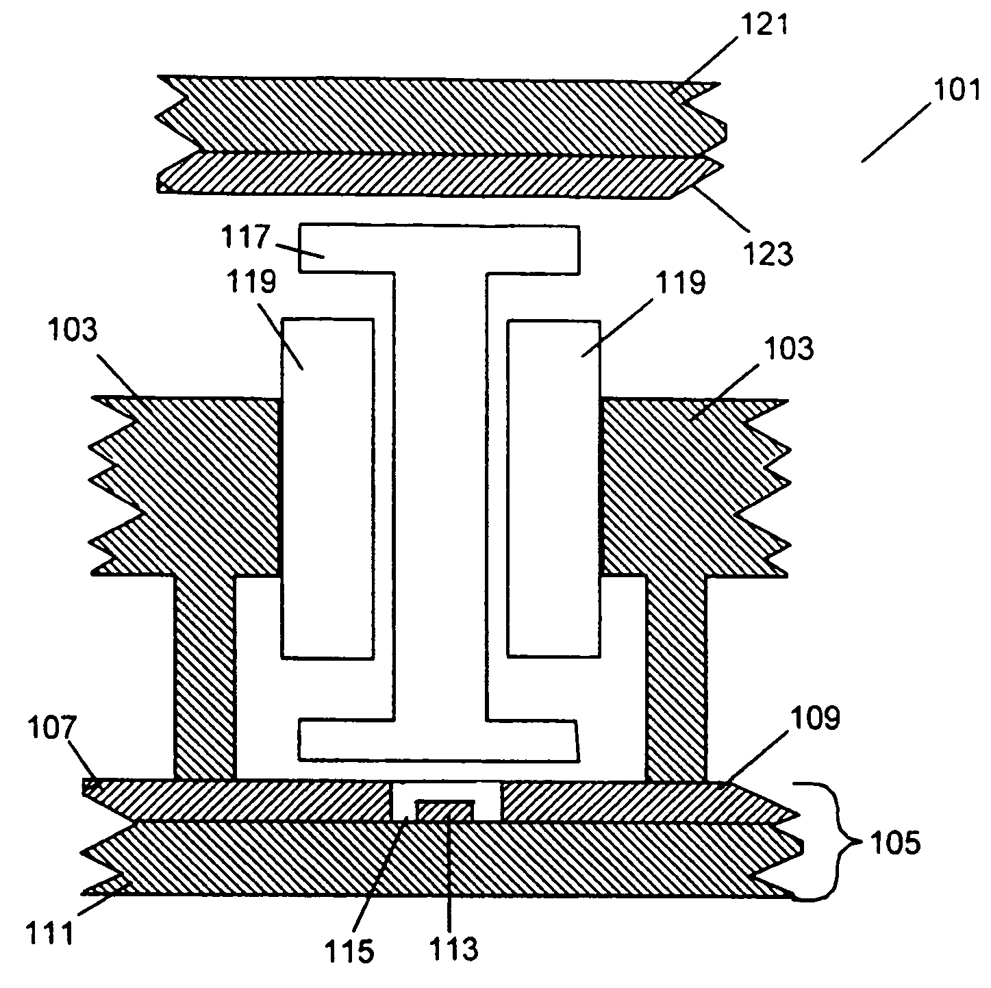
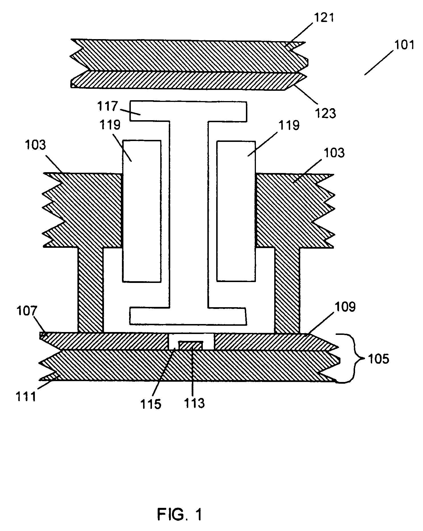
[0029] Turning to the drawings, wherein like reference numerals refer to like elements, the structure of a switch assembly according to various embodiments of the invention will be discussed, after which the fabrication of various switch components according to embodiments of the invention will be addressed. FIG. 1 shows a cross-sectional side view of an example microelectromechanical switch assembly 101 according to an embodiment of the invention. In particular, the switch assembly 101 in this embodiment of the invention comprises a frame 103 preferably fabricated of a substantially insulating material. The frame 103 is fixed to a base 105 comprising, at least in the vicinity of the switch 101, first and second terminals labeled 107 and 109 respectively fixed to a substrate 111. While shown in cross-section, the frame 103 may be of round, square or other configuration as viewed from above or below.

[0030] The first and second terminals or switch contacts 107, 109 are preferably fab...


PUM


Abstract

An improved microelectromechanical switch assembly comprises a linearly movable switch rod constrained via a switch bearing, the switch rod being actuated by electrostatic deflection. Movement of the switch rod to one end of its travel puts the switch assembly in a closed state while movement of the switch rod to the other end of its travel puts the switch assembly in an open state. In an embodiment of the invention, one or both of the switch rod and the switch bearing are fabricated of a carbon nanotube. The improved microelectromechanical switch assembly provides low insertion loss and long lifetime in an embodiment of the invention.

Description

FIELD OF THE INVENTION [0001] This invention relates generally to electronic switching and, more particularly, relates to a nanotube-based electronic switch having small dimensions and low switching friction and switching power requirements. BACKGROUND [0002] The increasing miniaturization of computer digital circuitry and other components has enabled a corresponding increase in computer power and decrease in the cost of creating powerful computing devices. However, certain critical components have not progressed as rapidly with respect to miniaturization, and the effects of this lag are beginning to limit the overall miniaturization of computing devices. For example, electronic switches (as opposed to purely solid state electrical switches such as transistors) are inherently mechanical in nature, and as such rely on forming and shaping steps that are not critical with respect to purely electrical systems. [0003] Before discussing microelectromechanical switch technology, a brief di...

Claims


Application Information

Patent Timeline
IPC IPC(8): H01H51/22
CPCH01H1/0094Y10S977/709Y10S977/731Y10S977/743Y10S977/745Y10S977/932
Inventor BUSTA, HEINZ H.WYLIE, IAN W.SNIDER, GARY W.
Owner CABOT MICROELECTRONICS CORP
Why Eureka
Try Eureka