
An all-optical packet switching switch based on microring resonator

A technology of micro-ring resonator and optical packet switching, which is applied in the field of optical information, can solve the problems of poor stability, bulky optical system, and inability to adapt to optical fiber communication, and achieve the effect of reducing switching power and huge application potential

Inactive Publication Date: 2018-09-21
HANGZHOU DIANZI UNIV
View PDF3 Cites 0 Cited by
  • Summary
  • Abstract
  • Description
  • Claims
  • Application Information

AI Technical Summary

Problems solved by technology

[0002] The traditional optical system is bulky and has poor stability, which cannot meet the needs of the development of modern optical fiber communication

Method used


Image

  • An all-optical packet switching switch based on microring resonator
  • An all-optical packet switching switch based on microring resonator

Examples


Embodiment Construction

[0014] The preferred embodiments of the present invention will be described in detail below in conjunction with the accompanying drawings.

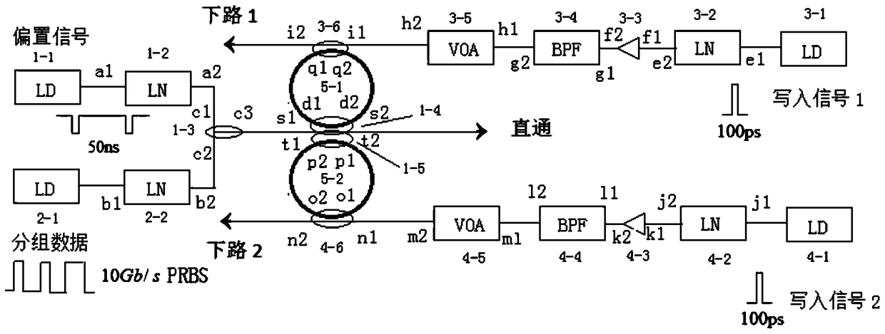
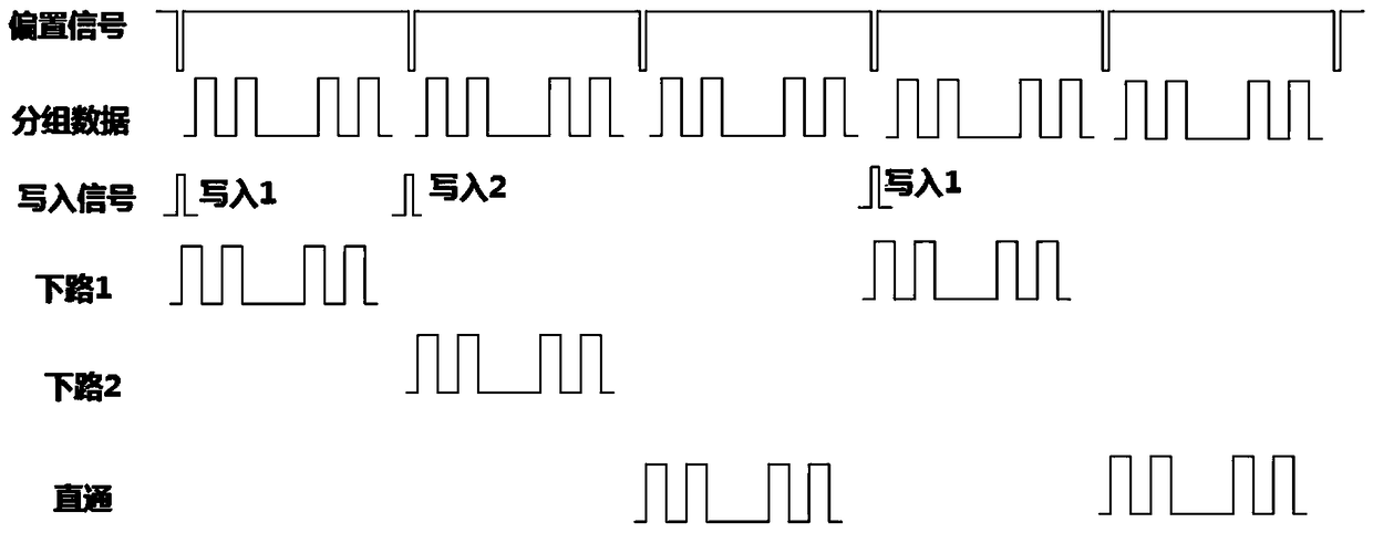
[0015] Such as Figure 1-2 As shown, the all-optical packet switching switch based on the microring resonator in this embodiment includes a bias signal source 1-1, a packet data stream 2-1, a first write signal source 3-1, and a second write signal source 4-1. The first lithium niobate modulator 1-2, the second lithium niobate modulator 2-2, the third lithium niobate modulator 3-2, the fourth lithium niobate modulator 4-2, WDM Multiplexer 1-3, first coupler 1-4, second coupler 1-5, third coupler 3-6, fourth coupler 4-6, first erbium-doped fiber amplifier 3-3, second Two erbium-doped fiber amplifiers 4-3, first bandpass filter 3-4, second bandpass filter 4-4, first variable optical attenuator 3-5, second variable optical attenuator 4-5 , the first microring resonator 5-1, and the second microring resonator 5-2.

[0016] The bias signal ...


PUM


Abstract

The invention discloses an all-optical packet switching switch based on micro-ring resonant cavities. A bias signal source is connected with a wavelength division multiplexer through a lithium niobate modulator 1; a packet data flow is connected with the wavelength division multiplexer through a lithium niobate modulator 2; the wavelength division multiplexer is connected with two couplers; and straight-through light is output through a port of a second coupler. A micro-ring resonant cavity 1 is coupled with two straight waveguide arms through a third coupler and a first coupler; and the light of the micro-ring resonant cavity 1 is input from a port of the first coupler, and output from another port. A micro-ring resonant cavity 2 is coupled with the two straight waveguide arms through a fourth coupler and the second coupler; and the light of the micro-ring resonant cavity 2 is input from one port of the second coupler, and output from another port. Write-in signal sources, the lithium niobate modulators, erbium-doped optical fiber amplifiers, band-pass filters and variable optical attenuators are connected in sequence; the variable optical attenuators are connected with the couplers, and light is output from the ports of the couplers; and light of each micro-ring resonant cavity is input from one port of the coupler and output from anther port.

Description

technical field [0001] The invention belongs to the technical field of optical information, and in particular relates to an all-optical packet switching switch based on a microring resonant cavity. Background technique [0002] The traditional optical system is bulky and has poor stability, which cannot meet the needs of the development of modern optical fiber communication. In order to realize the all-optical network, more and more scientific workers are committed to finding some optical devices with small size, simple structure and stable performance, and the microring resonator combines these advantages, and is one of the widely researched optical devices. . So far, the industry has developed a variety of optical devices based on microring resonators, such as all-optical switches, filters, optical delays, wavelength conversion, dispersion compensation, lasers, and so on. Light transmission in the nonlinear microring resonator has bistable characteristics, that is, one i...

Claims


Application Information

Patent Timeline
Patent Type & Authority Patents(China)
IPC IPC(8): G02B6/35G02B6/293
CPCG02B6/29338G02B6/354G02B6/356
Inventor 李齐良宋俊峰陈心李舒琴唐向宏胡淼魏一振周雪芳卢旸杨国伟
Owner HANGZHOU DIANZI UNIV
Learn More