Air-core microwave ablation antennas

a microwave ablation and air core technology, applied in the field of tissue resection, coagulation and hemostasis, and tissue delivery of microwave energy, can solve the problems of unfavorable patient safety, unwanted tissue necrosis, and heat generation, and achieve the effect of large power, without increasing the diameter of the feeding cable or the antenna

Active Publication Date: 2006-12-07
NEUWAVE MEDICAL
View PDF24 Cites 110 Cited by
  • Summary
  • Abstract
  • Description
  • Claims
  • Application Information

AI Technical Summary

Benefits of technology

[0008] This present disclosure relates to a method and device for the delivery of microwave (e.g. approximately 300 MHz and higher frequencies) power to an antenna through a coaxial cable having air or other gases (CO2, argon, helium, etc.) as the dielectric core. The device uses small mechanical supports made of low-loss mat...

Problems solved by technology

Limitations of the above techniques center on the power rating and diameter of the coaxial cable used to feed the antenna, as well as microwave losses inside the coaxial cable dielectric core.
Losses inside the coaxial cable dielectric core cause heat to be generated when large microwave powers are applied.
This causes undue heating of the feeding cable, which causes unwanted necrosis of tissue near the feed cable and is undes...

Method used


Image

  • Air-core microwave ablation antennas
  • Air-core microwave ablation antennas
  • Air-core microwave ablation antennas

Examples


Embodiment Construction

)

[0019] While the invention is susceptible of embodiment in many different forms, there is shown in the drawings and will be described herein in detail one or more embodiments of the present disclosure. It should be understood, however, that the present disclosure is to be considered an exemplification of the principles of the invention, and the embodiment(s) illustrated is / are not intended to limit the spirit and scope of the invention and / or the claims herein.

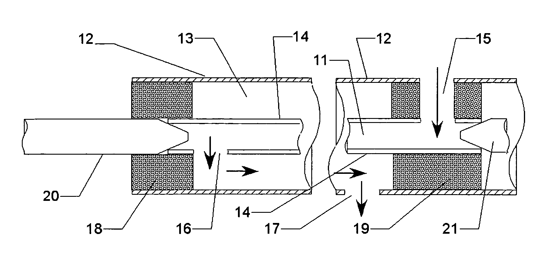
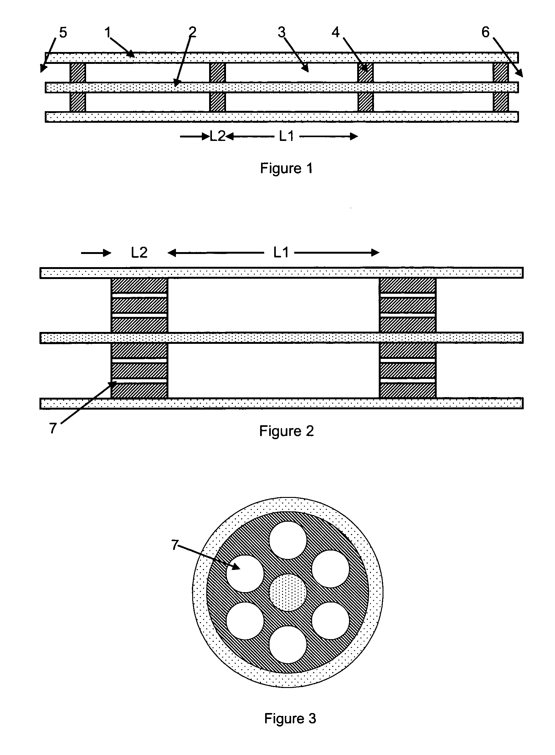
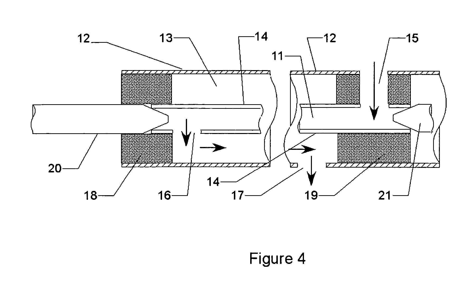
[0020] With reference to the drawings, the co-axial cable of the preferred embodiment of the present disclosure is shown. It should be understood that the cable can be of any suitable length, and the drawings figures are not intended to limit the length of the cable to the specific length illustrated or any specific length. Instead, it should be understood that only a representative portion or section of cable is illustrated.

[0021]FIG. 1 illustrates a semi-rigid coaxial cable, preferably constructed of copper or silver, uti...


PUM


Abstract

A method and device delivers microwave power to an antenna through a coaxial cable utilizing air or other gases as its dielectric core. The cable includes supports made of low-loss materials to keep the inner conductor centered in the cable, and defining spaces therebetween for the air or gas. Channels in the supports allow the air or gas to circulate in the cable. The gas may be chilled or cooled to provide an addition level of heat dissipation. The device enables delivery of large amounts of power to tissue without undue heating of the feed cable or peripheral tissues, and without increasing the diameter of the feeding cable or antenna, keeping the antenna safe for percutaneous use.

Description

CLAIM OF PRIORITY [0001] This application is a Continuation-In-Part of co-pending U.S. Non-Provisional patent application entitled “Triaxial Antenna for Microwave Tissue Ablation” filed Apr. 29, 2004 and assigned U.S. application Ser. No. 10 / 834,802, the entire disclosure of which is hereby herein incorporated by reference. [0002] This application further claims priority to U.S. Provisional Patent Applications entitled “Segmented Catheter for Tissue Ablation” filed May 10, 2005 and assigned U.S. application Ser. No. 60 / 679,722; “Microwave Surgical Device” filed May 24, 2005 and assigned U.S. Application Ser. No. 60 / 684,065; “Microwave Tissue Resection Tool” filed Jun. 24, 2005 and assigned U.S. application Ser. No. 60 / 690,370; “Cannula Cooling and Positioning Device” filed Jul. 25, 2005 and assigned U.S. application Ser. No. 60 / 702,393; “Intralumenal Microwave Device” filed Aug. 12, 2005 and assigned U.S. application Ser. No. 60 / 707,797; “Air-Core Microwave Ablation Antennas” filed ...

Claims


Application Information

Patent Timeline
IPC IPC(8): A61B18/18A61N1/00
CPCA61B18/18A61B18/1815A61N1/06A61B2018/00023A61B2018/00017
Inventor BRACE, CHRISTOPHER L.VAN DER WEIDE, DANIEL WARRENLAESEKE, PAUL F.LEE, FRED T. JR.
Owner NEUWAVE MEDICAL
Why Eureka
Try Eureka