Pedicle screw, cervical screw and rod

a cervical screw and pedicle screw technology, applied in the field of pedicle screw, cervical screw and rod, can solve the problems of reducing the purchase strength of the screw to the bone, reducing the degree of freedom in articulation, and affecting the treatment

Inactive Publication Date: 2006-12-07
ACCELERATED INNOVATION
View PDF16 Cites 178 Cited by
  • Summary
  • Abstract
  • Description
  • Claims
  • Application Information

AI Technical Summary

Benefits of technology

[0016]FIG. 4 is a side view of a pedicle screw that may be employed in the system for immobilization of the spine of FIG. 1 in accordance with one or more embodiments of the present invention;
[0017]FIG. 5 is a cross sectional view of a threaded portion of a pedicle screw that may be employed in the system for immobilization of the spine of FIG. 1 and that exhibits certain thread purchase properties in accordance with one or more embodiments of the present invention; and
[0018]FIG. 6 is a cross sectional view of a pedicle screw and tulip that may be employed in the system for immobilization of the spine of FIG. 1 and that exhibit certain articulation angle properties in accordance with one or more embodiments of the present invention.

Problems solved by technology

However, in many cases, and in particular, in cases involving fusion across the lumbosacral articulation and when there are many levels involved, pseudoarthrosis is a problem.
A common problem with spinal fixation is the question of how to secure the fixation device to the spine without damaging the spinal cord.
The problem with conventional pedicle screws and rods is that they are relatively large, resulting in reduced degrees of freedom in terms of articulation, reduced purchase strength of the screw to the bone, reduced degrees of freedom in terms of positioning the pedicle screws, rod, and connecting means to a particular patient.
Titanium, however, cannot withstand high bending stresses as compared with other metals, such as steel alloys (e.g., stainless steel) and cobalt chromium.

Method used


Image

  • Pedicle screw, cervical screw and rod
  • Pedicle screw, cervical screw and rod
  • Pedicle screw, cervical screw and rod

Examples


Embodiment Construction

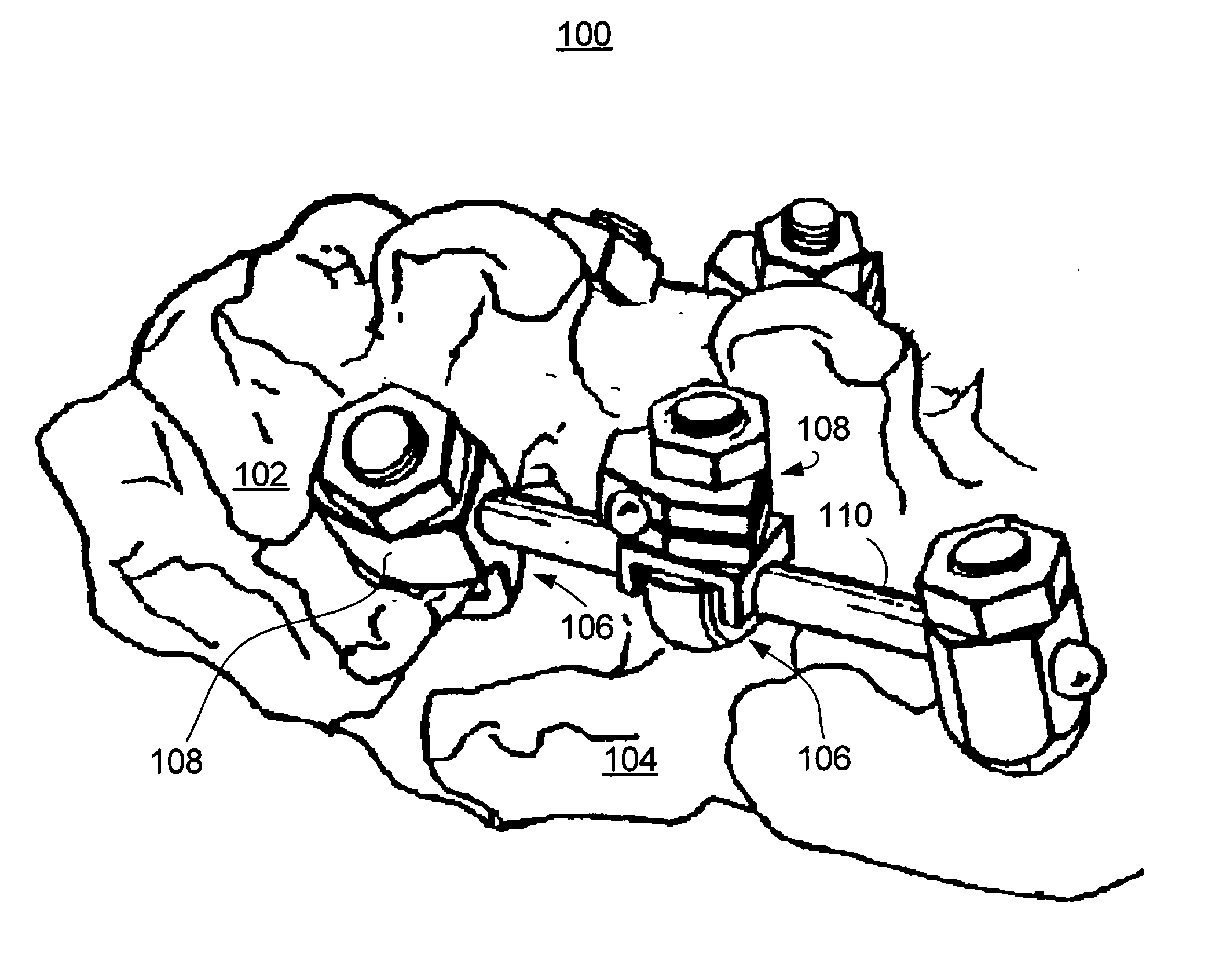
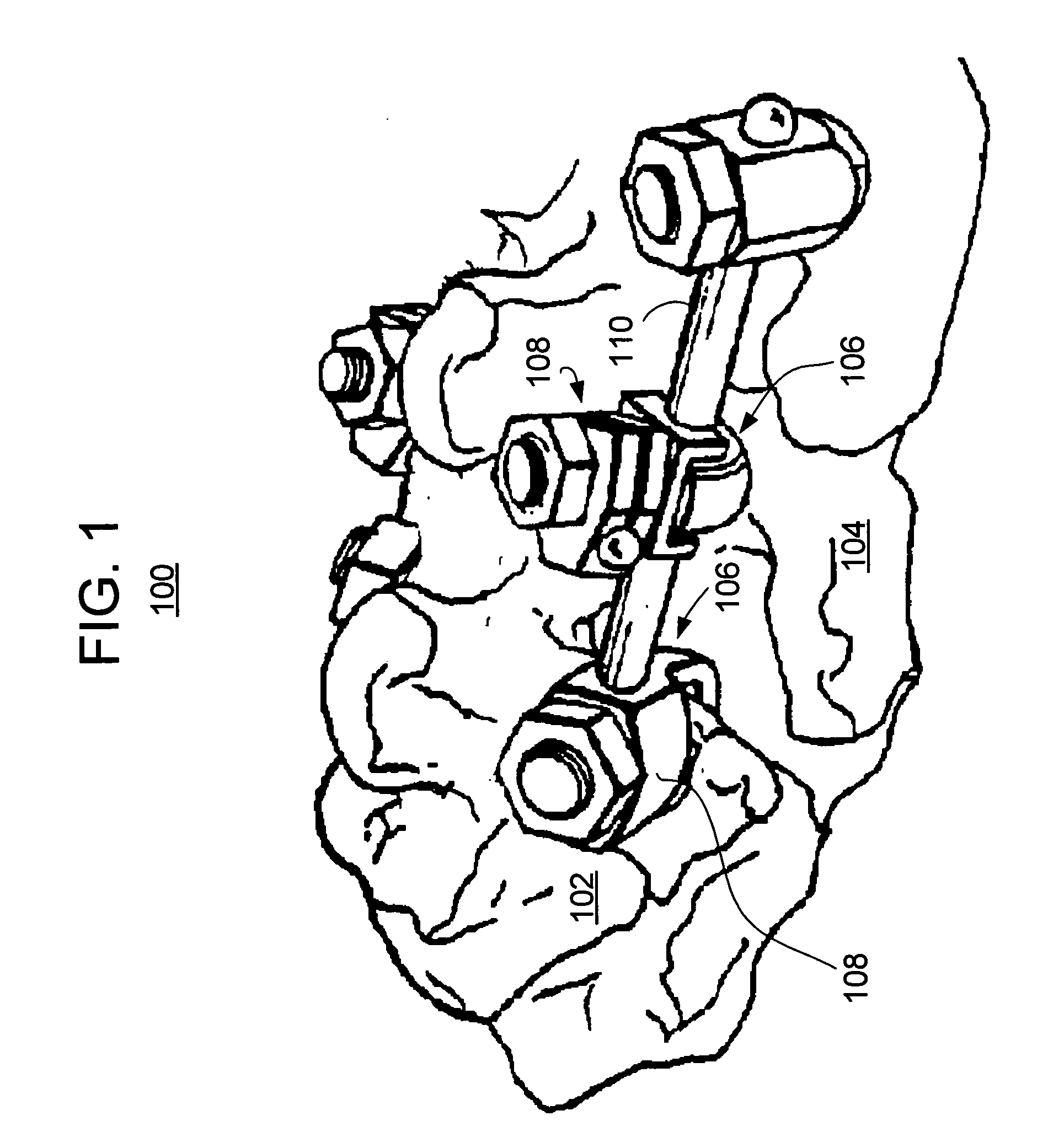
[0019] With reference to the drawings wherein like numerals indicate like elements there is shown in FIG. 1 an anchoring system 100 for internal fixation of respective vertebral bones 102, 104 of a patient. The system 100 includes a plurality of pedicle screws 106 and anchor seats (or tulips) 108 that cooperate to fix a portion of a rod 110 to a bone. Although in some embodiments of the invention the specific design details of the pedicle screws 106 and anchor seats 108 are not of significant concern, it is noted here that the anchor seats 104 may include a socket and a locking element, and the pedicle screw 106 may include a head. The socket is preferably sized and shaped to receive a corresponding contour of the head of the pedicle screw 106 to permit articulation of the anchor seat 108 relative to the pedicle screw 106. The locking element of the anchor seat 108 fixes the relative positions of the pedicle screw 106 and the rod 110 after all the components are in a desired positio...


PUM

PropertyMeasurementUnit
diameteraaaaaaaaaa
diameteraaaaaaaaaa
diameteraaaaaaaaaa

Abstract

A rod for interconnecting at least two pedicle screws implanted in adjacent vertebrae of a spine and/or the rod itself includes a metal or metal alloy of substantial nickel content; and an outer layer of ceramic coating the metal such that exposure of the nickel to a patient is inhibited.

Description

BACKGROUND OF THE INVENTION [0001] This invention relates generally to an apparatus for immobilization of the spine, and more particularly, to an apparatus for posterior internal fixation of the spine as well as to a method of therapy which utilizes the device. For example, the present invention relates to pedicle screws and rods for fixing vertebrae in a spine. [0002] Various methods of spinal immobilization have been known and used during this century in the treatment of spinal instability and displacement. One treatment for spinal stabilization is immobilization of the joint by surgical fusion, or arthrodesis. This method has been known since its development in 1911 by Hibbs and Albee. However, in many cases, and in particular, in cases involving fusion across the lumbosacral articulation and when there are many levels involved, pseudoarthrosis is a problem. It was discovered that immediate immobilization was necessary in order to allow a bony union to form. [0003] Internal fixat...

Claims


Application Information

Patent Timeline
Patent Type & Authority Applications(United States)
IPC IPC(8): A61F2/30
CPCA61B17/7002A61B17/7032A61B17/7037A61L31/086A61B2017/00831A61L31/022A61B17/7038
Inventor ZUBOK, RAFAILKVITNITSKY, MIKHAIL
Owner ACCELERATED INNOVATION
Why Eureka
Try Eureka