Vacuum apparatus and method using ultraviolet radiation for sanitization

a vacuum apparatus and ultraviolet radiation technology, applied in the direction of auxillary pretreatment, separation process, filtration separation, etc., can solve the problems of bacteria remaining a constant ongoing problem, unable to be trapped in conventional filter means, and causing the discharge of contaminated air

Inactive Publication Date: 2006-12-14
HELSEL DARIN R
View PDF3 Cites 14 Cited by
  • Summary
  • Abstract
  • Description
  • Claims
  • Application Information

AI Technical Summary

Benefits of technology

[0017] Vacuum cleaners comprise several various design features that are common to virtually all vacuums. An intake port is provided, through which air rushes in due to the fact that the air pressure further up inside the vacuum cleaner has been reduced. The air intake is positioned close to the surface which is desired to be swept or have debris removed. The fast moving air stream moving into the vacuum, when placed adjacent to the surface that is being treated, will cause debris and any particulate matter to also move into the air stream and be forced into the vacuum cleaner. Brushes and other physically engaging members may agitate the surface being cleaned to help loosen debris so that it can be carried by the air stream into the vacuum.
[0035] It is a further object of this invention to provide an industrial vacuum cleaner, having a canister or tank collector means, with the capability of exposing bacteria to a sufficient level of ultraviolet radiation, both as to intensity and to duration, so as to sterilize any bacterial contamination prior to the ejection of any such bacteria from the vacuum cleaner.

Problems solved by technology

The fast moving air stream moving into the vacuum, when placed adjacent to the surface that is being treated, will cause debris and any particulate matter to also move into the air stream and be forced into the vacuum cleaner.
Larger filters have given rise to an increased particular matter removal from the ejected air, but bacteria remains a constant ongoing problem due to its extremely small size.
Much of the bacteria that is collected during the vacuuming process has such a small diameter that it is unable to be trapped in conventional filter means.
Electronic filters utilizing ionic attraction have met with some success, but on a conventional vacuum cleaner, the filtration system necessary to physically filter out unwanted bacteria is either too cumbersome or too expensive for the average consumer.

Method used


Image

  • Vacuum apparatus and method using ultraviolet radiation for sanitization
  • Vacuum apparatus and method using ultraviolet radiation for sanitization
  • Vacuum apparatus and method using ultraviolet radiation for sanitization

Examples


Embodiment Construction

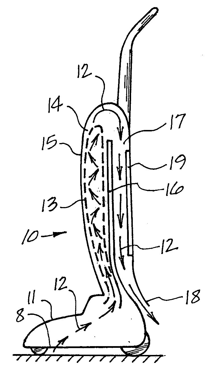
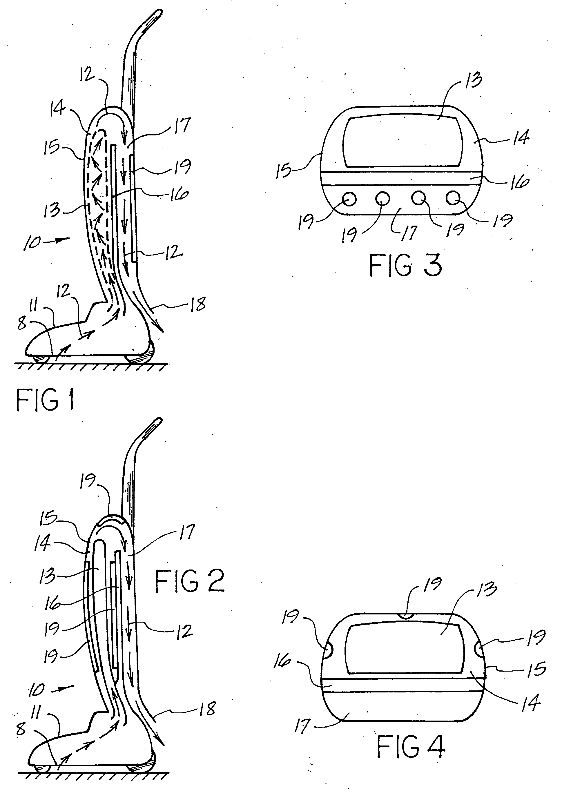
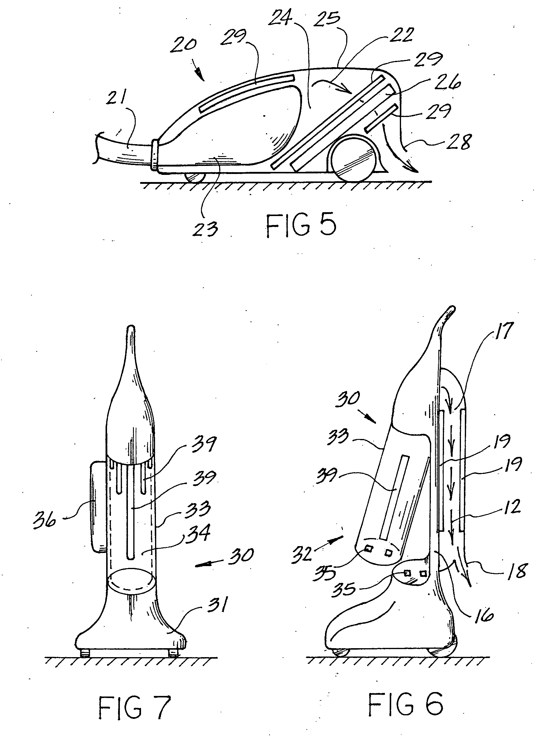
[0049] Referring to FIG. 1, a typical upright bag vacuum 10 is shown, in which the head 11 is placed adjacent to the surface desired to be vacuumed, so that intake port 8 is adjacent to said surface. All vacuums described herein and below have an intake port, through which air first moves into the vacuum cleaner. The air entering into the vacuum cleaner is generally contaminated with biological matter that can pose a health hazard if breathed or redeposited in the area being vacuumed.

[0050] Air enters the intake port 8 and is directed along an air pathway 12 into the collector or bag 13, which traps particulate matter of certain sizes that are present in the air stream 12, as the air stream moves through the lining of the bag 13. As is shown in FIG. 1, the bag 13 is fully contained within a first chamber 14, where said chamber 14 comprises a portion of the interior of the upright canister 15. The bag 13 provides a filter means, whereby air escaping through the porous openings in th...


PUM

PropertyMeasurementUnit
sizesaaaaaaaaaa
volumesaaaaaaaaaa
lengthaaaaaaaaaa

Abstract

This invention deals specifically with the use of ultraviolet light emitters within a vacuum cleaner, where the lights are used to neutralize bacterial contamination. The air and debris entering into the vacuum is exposed to one or more ultraviolet light sources, with the resulting radiation causing the bacterial contaminants to be neutralized. The vacuum used may be an upright bag vacuum, an upright bagless vacuum, a floor type vacuum, or a shop type vacuum. Multiple chambers are provided, in which the lights are disposed in secondary chambers, in addition to any lights used at the point of initial filtration.

Description

BACKGROUND OF THE INVENTION [0001] Previous inventions have recognized the usefulness of ultraviolet light radiation for sanitization purposes. Numerous uses have been recognized for the treatment of objects and air volumes. Ultraviolet light has been used to sterilize objects and air masses within buildings. The treatment of air with ultraviolet light within a building air duct is an attempt to cure the problem of airborne bacteria after it has already entered into an airmass. The term “bacteria” should be understood to be illustrative of any type of biological contaminant that is able to be neutralized or killed through exposure to ultraviolet light radiation. Household vacuum cleaners generally have the most opportunity and propensity of any appliance to move bacteria from the floor or carpet back into the air, as a result of inadequate filtering techniques. The treatment of the airflow through the vacuum cleaner itself is of primary importance in achieving proper sanitation. Whi...

Claims


Application Information

Patent Timeline
Patent Type & Authority Applications(United States)
IPC IPC(8): B01D46/00
CPCA47L7/04
Inventor HELSEL, DARIN R.
Owner HELSEL DARIN R
Why Eureka
Try Eureka