Assembly and method of alternative pumping using hollow rods without tubing

a technology of hollow rods and tubing, which is applied in the direction of positive displacement liquid engines, wellbore/well accessories, sealing/packing, etc., can solve the problems of rod and/or production tubing breaking, damage to the system, and no new oil fields found, etc., to achieve easy assembly, installation and handling, and simple and robust

Inactive Publication Date: 2006-12-14
YPF SA
View PDF13 Cites 28 Cited by
  • Summary
  • Abstract
  • Description
  • Claims
  • Application Information

AI Technical Summary

Benefits of technology

[0022] An important object of the invention is to provide a simple and robust bottom set, able to house and anchor reciprocating pumps of any size according to the casing diameter.
[0052] a hollow polished rod consisting in a, preferably but not limited to, chromeplated hollow rod in its external wall. Such polished rod is coupled by its bottom end to the free upper end of the hollow rod string, preferably by means of a connecting sleeve within the well, and it prolongs outside the well coupling itself by its upper end to the production bridge that links the polished rod to the surface driving tubing. Said polished rod is connected to means that impart the axial reciprocating pumping movement. A lubricating device is provided for allowing the polished rod to work lubricated, said device packing the annular space between the polished rod and the casing. Since the production fluid flows inside the polished rod, there is no possibility of loosing fluids due to failure in the gasket, which significantly reduces the environmental pollution risk;

Problems solved by technology

However, new oil fields have not been found, and oil and gas reservoirs have been reduced in the last three years.
The solid rods movement within the production tubing involves a frictional contact between both, thus producing the rod and / or production tubing break and damages to the system.
This problem increases in deviated or crooked holes.
The high number of interventions in holes due to this problem generates high maintenance costs and increased production losses.
In such system, the production tubing cost is a significant part of the total investment.
The conventional pumping system with production tubing provides low pumping efficiency due to its stretching and shortening, which occurs with the change of direction of the rod string between ascending and descending movement.
Another relevant disadvantage of the system is that, whenever a service on the pump is needed in the fixed tubing system (when due to its size the pump is fixed to the production tubing) it is necessary to remove the rod string and the production tubing, thus increasing the hole intervention and interruption times, with the corresponding rise in costs, and loss of production.
The great flexibility helps its coiling, however, it reduces the strength to absorb compression efforts and buckling during the ascending run, thus increasing the possibility of friction against casing walls, particularly in deep wells.
In addition, once broken, the continuous tubing must be bound by welding, thus reducing the resistance against weariness in said area.
This reduction is enhanced by the amount of splices, considerably reducing the life of the continuous tubing that may derive in a total change of it.
The continuous tubing system does not allow the use of vulcanized centralizers on the tubing body; only bayonet centralizers may be used, with no satisfactory results.
This arrangement increases the environmental pollution risks due to the possibility of high pressure, several bent parts and harsh environments that may produce a malfunction in the flexible tube.

Method used


Image

  • Assembly and method of alternative pumping using hollow rods without tubing
  • Assembly and method of alternative pumping using hollow rods without tubing
  • Assembly and method of alternative pumping using hollow rods without tubing

Examples


Embodiment Construction

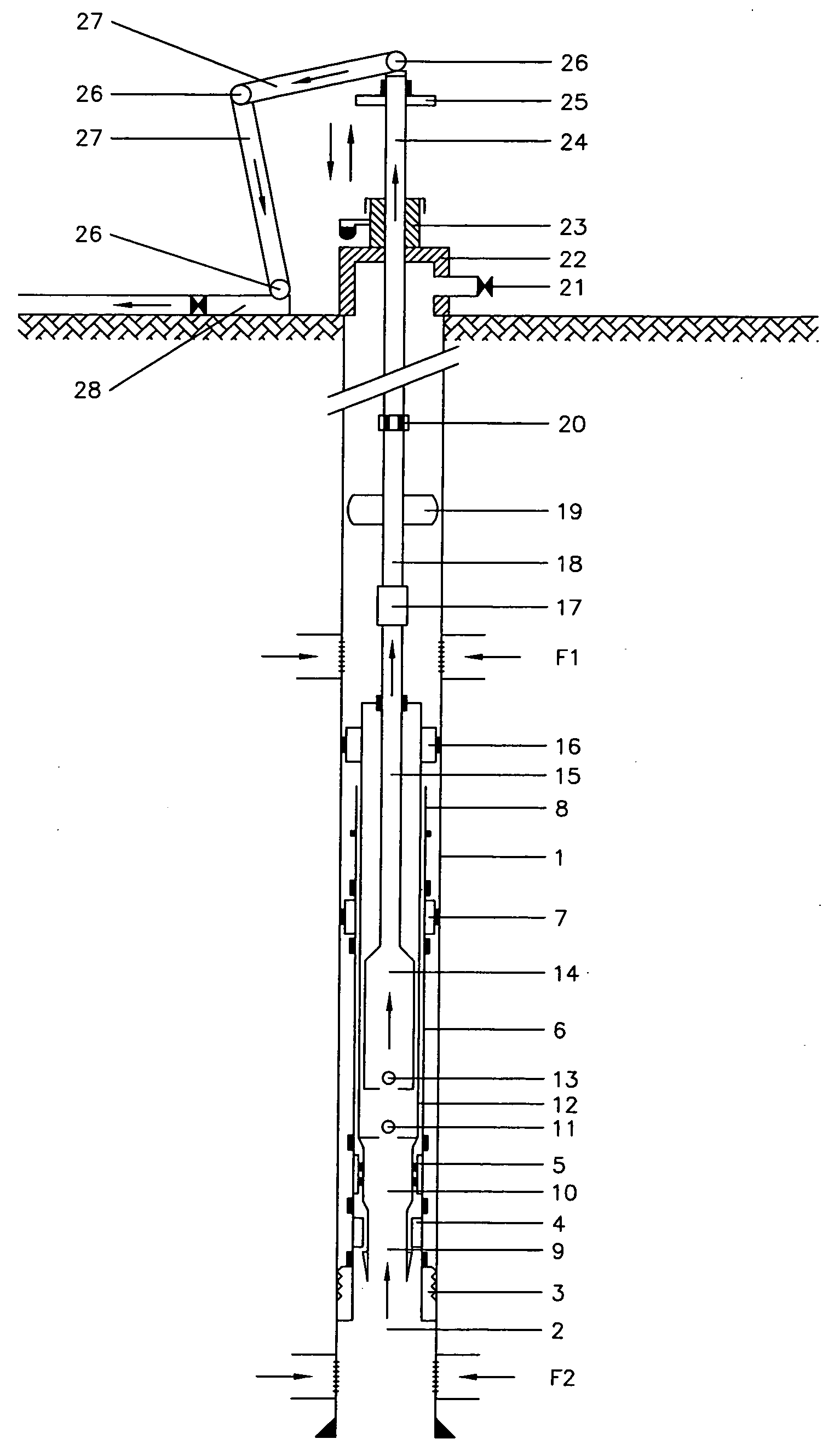
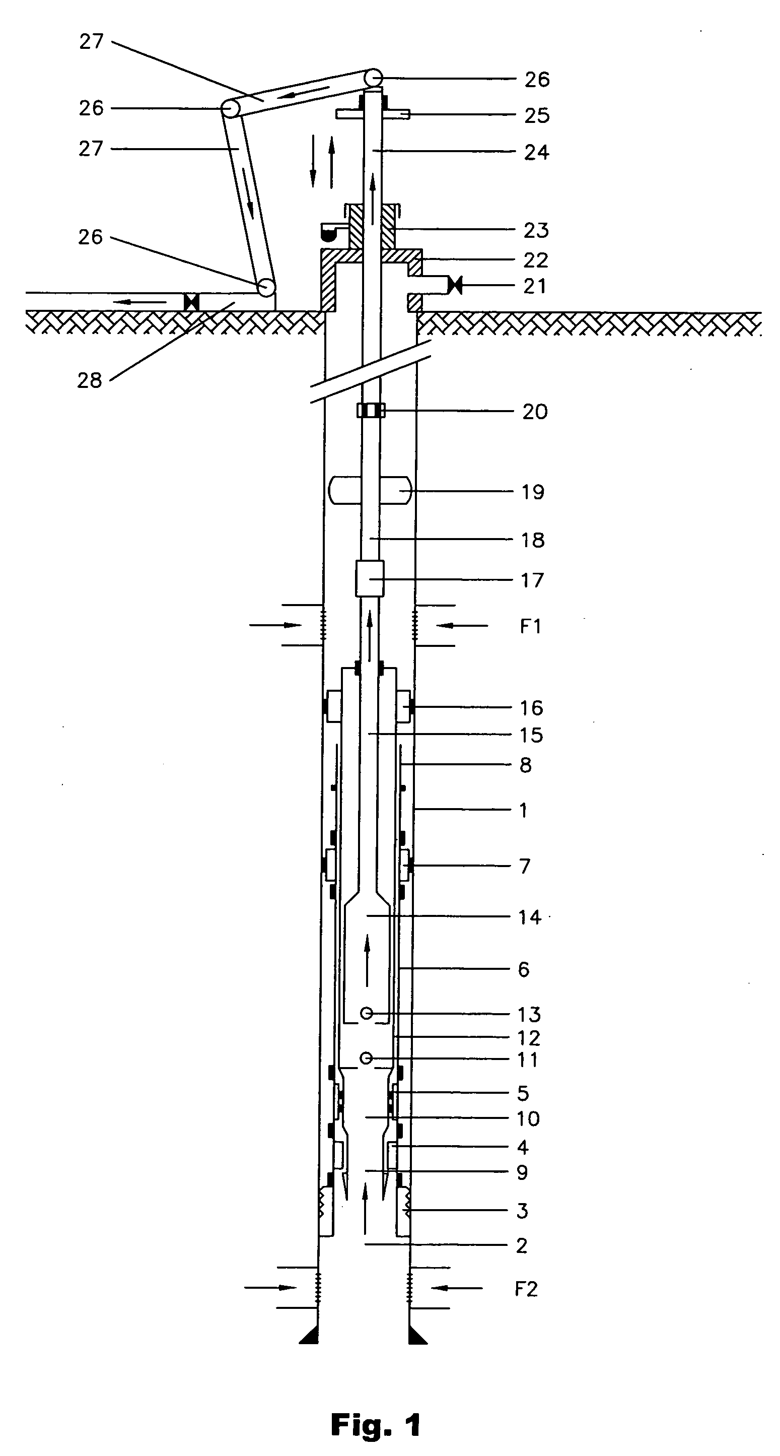
[0063]FIG. 1 shows a perforation made in an effluent producing geological formation containing, for instance, hydrocarbons. The borehole wall is lining by a casing tube 1. Preferably, the tube 1 is fixed or anchored to the borehole wall by a concrete layer injected in the annular space between the casing external face 1 and the borehole face. At pre-selected depths zones, according to previous geological studies, the casing and the concrete are perforated or drilled to allow the free entry of fluid from the reservoir. Two fluid access layers (F1, F2) at different depths are illustrated in FIG. 1. In this case, a multilayer exploitation is illustrated.

[0064] In general, as shown by the scheme of FIG. 1, the reciprocating axial pumping system of the present invention, combines a rigid well head 22 that provides a casing venting exit 21, a hollow sucker rod string 18 with centralizers 19, a reciprocating axial deep well pump and a stationary bottom set that allows to anchor the recipr...


PUM


Abstract

Assembly and method for extracting fluids, preferably crude oil, from a drilled well within a geological formation by means of reciprocating pumping with hollow sucker rods. The assembly includes: a) a stationary bottom set attached to the casing at the desired depth and providing the rod pump anchoring system; b) a reciprocating axial movement rod pump having an anchoring system and a centralizer; c) a centralized hollow rod string extending within the well, which is connected to the mobile member of the pump; d) a hollow polished rod connected to the hollow rod string and linked to a system that imparts the reciprocating axial movement to the pump; e) a production bridge connecting the polished rod to the driving tubing through rotating joints, and f) a rigid head that provides a venting exit of the annular space formed between the string and the casing.

Description

FIELD OF THE INVENTION [0001] The present invention relates to an assembly and method for extracting fluids, preferably crude oil, from a drilled well within a geological formation by means of reciprocating pumping with hollow sucker rods. In particular, the system comprises the use of a string of hollow centered rods, which are able to transport / extract the effluents to the surface through their inner bore and, at the same time, to impart the reciprocating axial movement in relation to the subsurface pump. BACKGROUND OF THE INVENTION [0002] The economical or strategic importance of oil, is evident, therefore the possibility of increasing the production, as well as the usable reservoirs, is extremely attractive. However, new oil fields have not been found, and oil and gas reservoirs have been reduced in the last three years. In addition, the cost reduction is a constant existing need in all industries in order to increase the competitivity and profitability of the companies. In the ...

Claims


Application Information

Patent Timeline
Patent Type & Authority Applications(United States)
IPC IPC(8): E21B43/00
CPCE21B17/046E21B17/1014E21B43/126F04B47/028F04B47/02F04B47/026E21B43/127
Inventor RUGGERI, JORGEBIANCHETTI, OMARSCARAMUZZA, JOSE L.
Owner YPF SA
Why Eureka
Try Eureka