Measuring device and method for determining relative positions of a positioning stage configured to be moveable in at least one direction

a technology of positioning stage and measuring device, which is applied in the direction of measuring device, using optical means, instruments, etc., can solve the problems of inability to create a hermetically sealed chamber to maintain a constant air pressure, inability to meet the requirements of measuring accuracy, and inability to determine changes. the effect of accuracy

Active Publication Date: 2006-12-14
VISTEC SEMICON SYST
View PDF4 Cites 69 Cited by
  • Summary
  • Abstract
  • Description
  • Claims
  • Application Information

AI Technical Summary

Benefits of technology

[0007] It is therefore an object of the present invention to provide and further develop a measuring device for determining relative positions of a positioning stage at least moveable in one direction of the initially mentioned type, by which the above mentioned problems are overcome. In particular it should be possible to achieve increased accuracy in determining changes in the ambient influences.

Problems solved by technology

The fluctuations in the readings due to wavelength variations, at ±0.1 μm, are no longer negligible with respect to the structures to be measured in typical measurements, such as in a coordinate measuring device on wafers and masks, and are therefore no longer acceptable for the required measuring accuracy.
The control accuracy of temperature and moisture has technical limits.
With a reasonable expenditure of effort, it is impossible to create a hermetically sealed chamber to maintain a constant air pressure, in particular since in the example of a coordinate measurement device it is necessary that the measuring objects can be exchanged simply and rapidly.
Even the operation of the loading door causes rapid pressure fluctuations.
Fluctuations of the air pressure within the chamber are caused by the measuring structure itself and are therefore not entirely avoidable.

Method used


Image

  • Measuring device and method for determining relative positions of a positioning stage configured to be moveable in at least one direction
  • Measuring device and method for determining relative positions of a positioning stage configured to be moveable in at least one direction
  • Measuring device and method for determining relative positions of a positioning stage configured to be moveable in at least one direction

Examples


Embodiment Construction

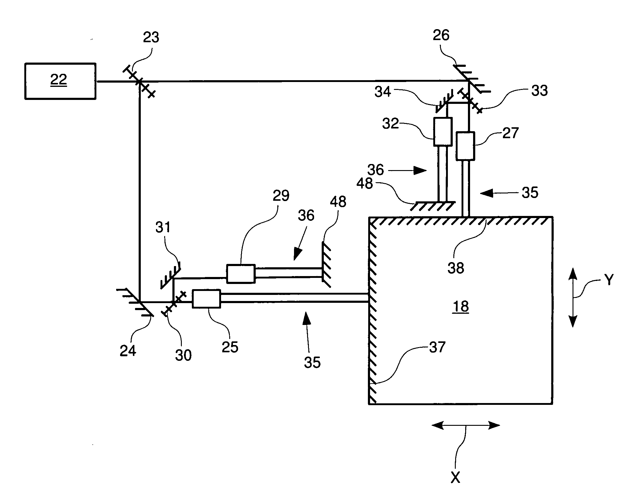
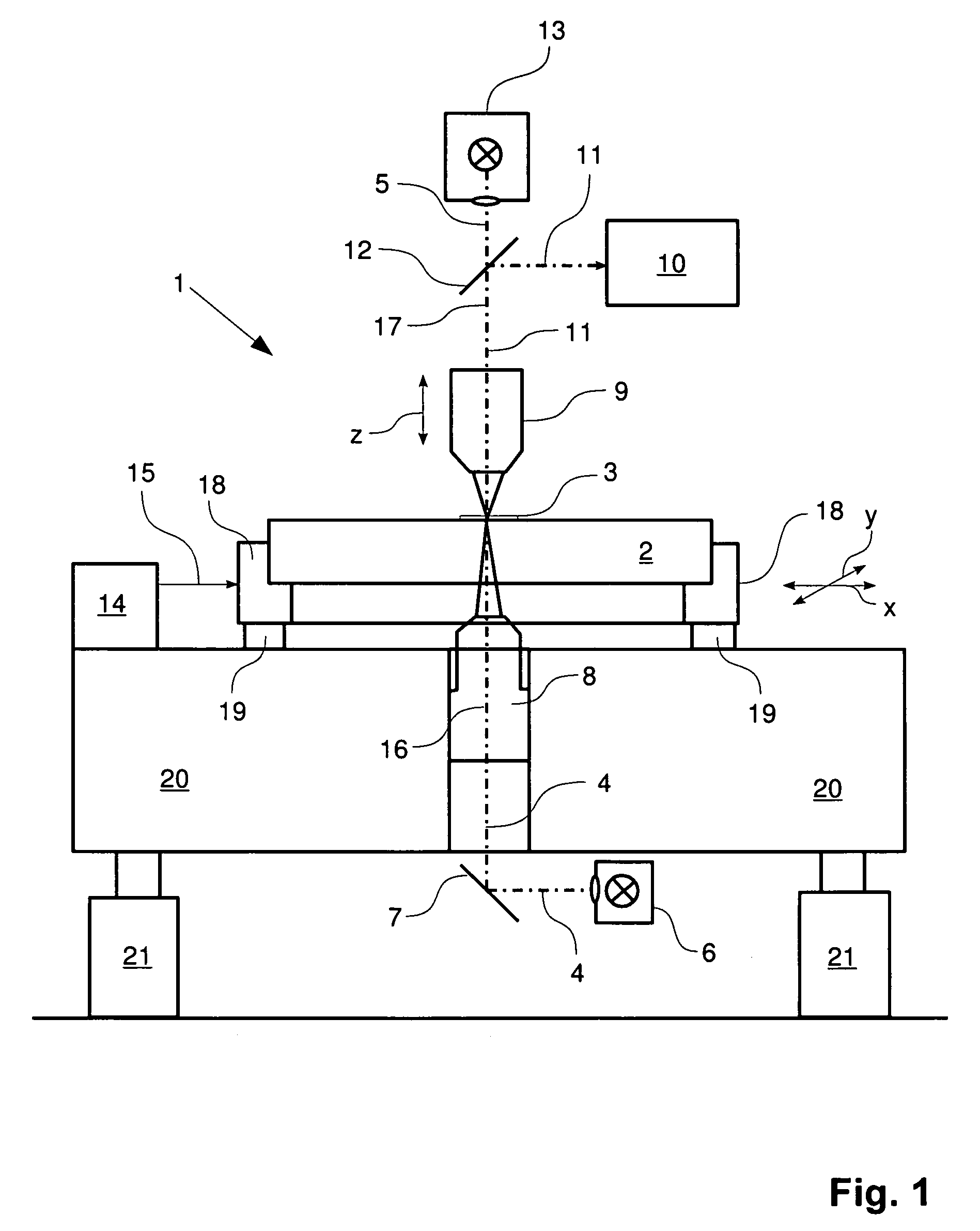
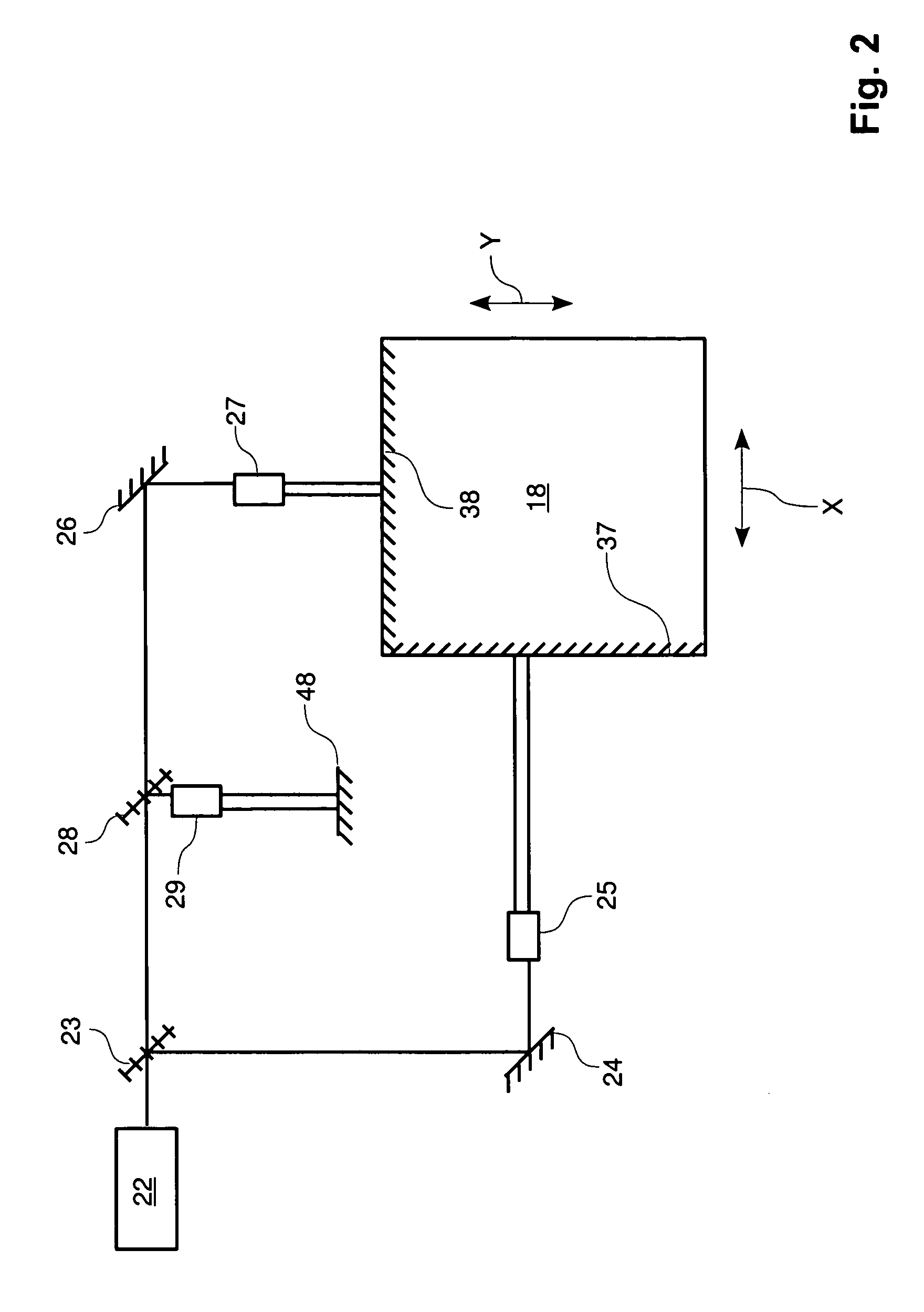
[0043] Components which are similar or the same are indicated with the same reference numerals throughout the figures. FIG. 1 shows a coordinate measuring device 1 with which it is possible to optically inspect objects 2. Object 2 shown in FIG. 1 is a mask, which can be of quartz glass for example. Structures 3 are applied to the mask, which are inspected with the coordinate measurement device 1. Coordinate measurement device 1 comprises two illumination beam paths 4 and 5, wherein illumination beam path 4 is for the transmitted-light mode and illumination beam path 5 is for the incident-light mode of coordinate measurement device 1. For the transmitted-light mode, a light source 6 is provided for emitting light in the near ultraviolet and which is reflected by mirror 7 towards an illumination optics configured in the form of a condenser 8. The light of illumination beam path 4 passes through object 2 and is at least substantially collected by imaging optics 9 and imaged onto detect...


PUM


Abstract

A measuring apparatus for determining relative positions of a positioning stage arranged in a moveable fashion in at least one direction by a predeterminable maximum traversing path. The measuring device comprises at least one interferometric measuring means and at least one interferometric correction means. An interferometric measuring means is operable with the laser light of a laser of at least one wavelength. Correction results can be generated with the interferometric correction means allowing conclusions to be drawn with respect to the actual wavelength of the laser light during a position determination of the positioning stage in order to take into account variations of the wavelength of the laser light, in particular due to ambient conditions, when evaluating the measuring results. The interferometric correction means is arranged proximate to the interferometric measuring means, and the proximity corresponds to a predeterminable portion of the maximum traversing path of the positioning stage.

Description

CROSS REFERENCE TO RELATED APPLICATIONS [0001] This application claims priority of German Patent Application No. 10 2005 023 085.7, filed May 13, 2005, and German Patent Application No. 10 2005 035 700.8, filed Jul. 27, 2005, which applications are incorporated herein by reference. FIELD OF THE INVENTION [0002] The present invention relates to a measuring device for determining relative positions of a positioning stage configured to be moveable in at least one direction by a predeterminable maximum traversing path. The measuring device comprises at least one interferometric measuring means and at least one interferometric correction means. An interferometric measuring means is for obtaining measuring results to determine relative positions of the positioning stage for a movement along a movement direction. An interferometric measuring means is operable with laser light of a laser of at least one wavelength. The interferometric correction means is for obtaining correction readings al...

Claims


Application Information

Patent Timeline
Patent Type & Authority Applications(United States)
IPC IPC(8): G01B9/02G01B11/02
CPCG01B9/0207G01B9/02021G01B2290/70G01B9/02018G01B9/02002
Inventor BOESSER, HANS-ARTURADAM, KLAUS-DIETER
Owner VISTEC SEMICON SYST
Why Eureka
Try Eureka