Communication control method and communication system to which the same is applied

a communication control and communication system technology, applied in the field of communication control methods and communication systems to which the same is applied, can solve the problems of high load status of cpu utilization, severe failures, and inability to operate, and achieve the effect of preventing the generation of a failure phenomenon and increasing load

Inactive Publication Date: 2006-12-14
FUJITSU LTD
View PDF16 Cites 13 Cited by
  • Summary
  • Abstract
  • Description
  • Claims
  • Application Information

AI Technical Summary

Benefits of technology

[0014] It is therefore an object of the present invention to provide a communication control method and a communication system to which the same is applied, for preventing generation of a failure phenomenon by reducing the number of received broadcast packets per unit of time, which becomes a cause of a higher load at an end host associated with a L2 loop when the number of received packets is too large.
[0020] Thus, the present invention can implement a communication control method and a communication system to which the same is applied, for preventing generation of a failure phenomenon by reducing the number of received broadcast packets per unit of time.

Problems solved by technology

In this way, since reception of broadcast packets generates interrupting processing at end hosts and network devices on network, a high-load status of CPU utilization is generated especially in PCs or network devices executing software processing, and severe failures are generated, such as inability of operation.

Method used


Image

  • Communication control method and communication system to which the same is applied
  • Communication control method and communication system to which the same is applied
  • Communication control method and communication system to which the same is applied

Examples


first embodiment

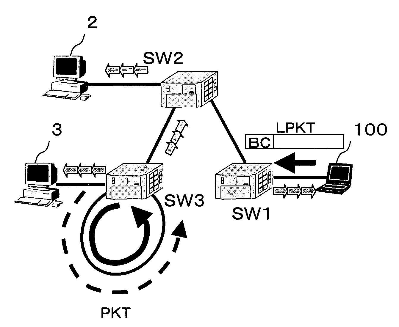
[0040]FIG. 3 is a diagram showing a configuration example of a subnet for describing the present invention. A relay switch SW is connected to end hosts 200A, 200B, and a loop switch LSW is connected ahead of the relay switch SW. It is assumed that the L2 loop is generated in this loop switch LSW and that the network is in a high-load status due to the generation of the L2 loop.

[0041] In order to dissolve the failure status, the inventive apparatus 100 is connected to the relay switch SW, as one of the hosts. FIG. 4 is a functional block diagram of a structure example of the inventive apparatus 100. FIG. 5 is a sequence flow for describing the inventive embodiment.

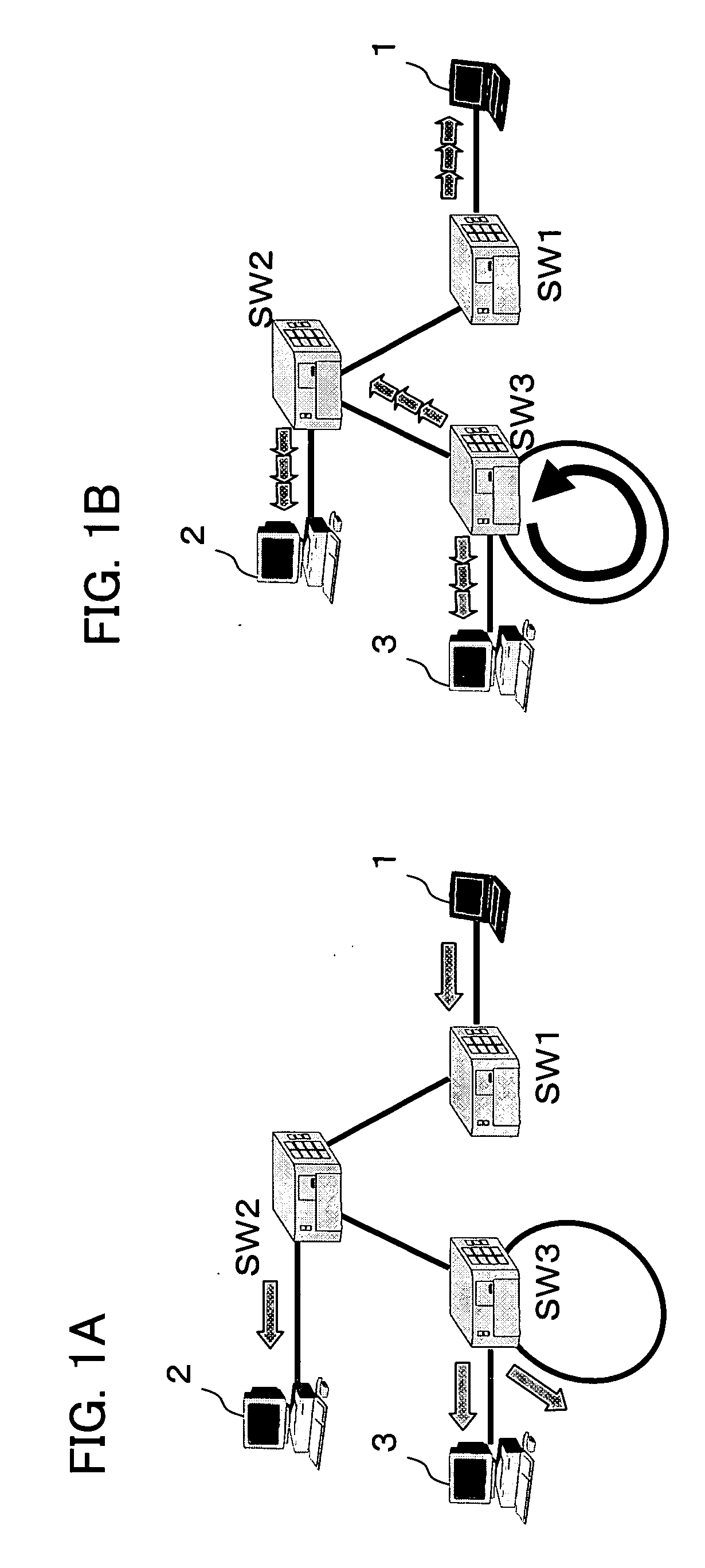
[0042] In the sequence flow shown in FIG. 5, when the end host 200A performs broadcast transmission of the short packet PKT, each node will be in a high-load status because the L2 loop is generated due to an improper connection in the loop switch LSW (P1).

[0043] In order to dissolve this status, the inventive apparatus 1...

second embodiment

[0056] The first embodiment determines a transmitted packet and the number of the packet by the input, default or fixed parameters without depending on the situation of the network. Contrary to this, a second embodiment is characterized by that the transmitted packet and the number of the packet are determined depending on the situation of the network.

[0057]FIG. 6 is a diagram showing a configuration of an inventive apparatus 100 corresponding to the second embodiment, adding a function for receiving packets to the apparatus configuration (FIG. 4) of the inventive apparatus 100 shown in the first embodiment.

[0058] In FIG. 6, a packet reception unit 105 has such functions as receiving broadcast packets through a network interface 103, recording lengths of the received packets in a monitor unit 106, recording MAC addresses of end hosts existing in network, calculating a reception rate, or recording a cycle of the received packets. If necessary, the packet reception unit 105 can have...

third embodiment

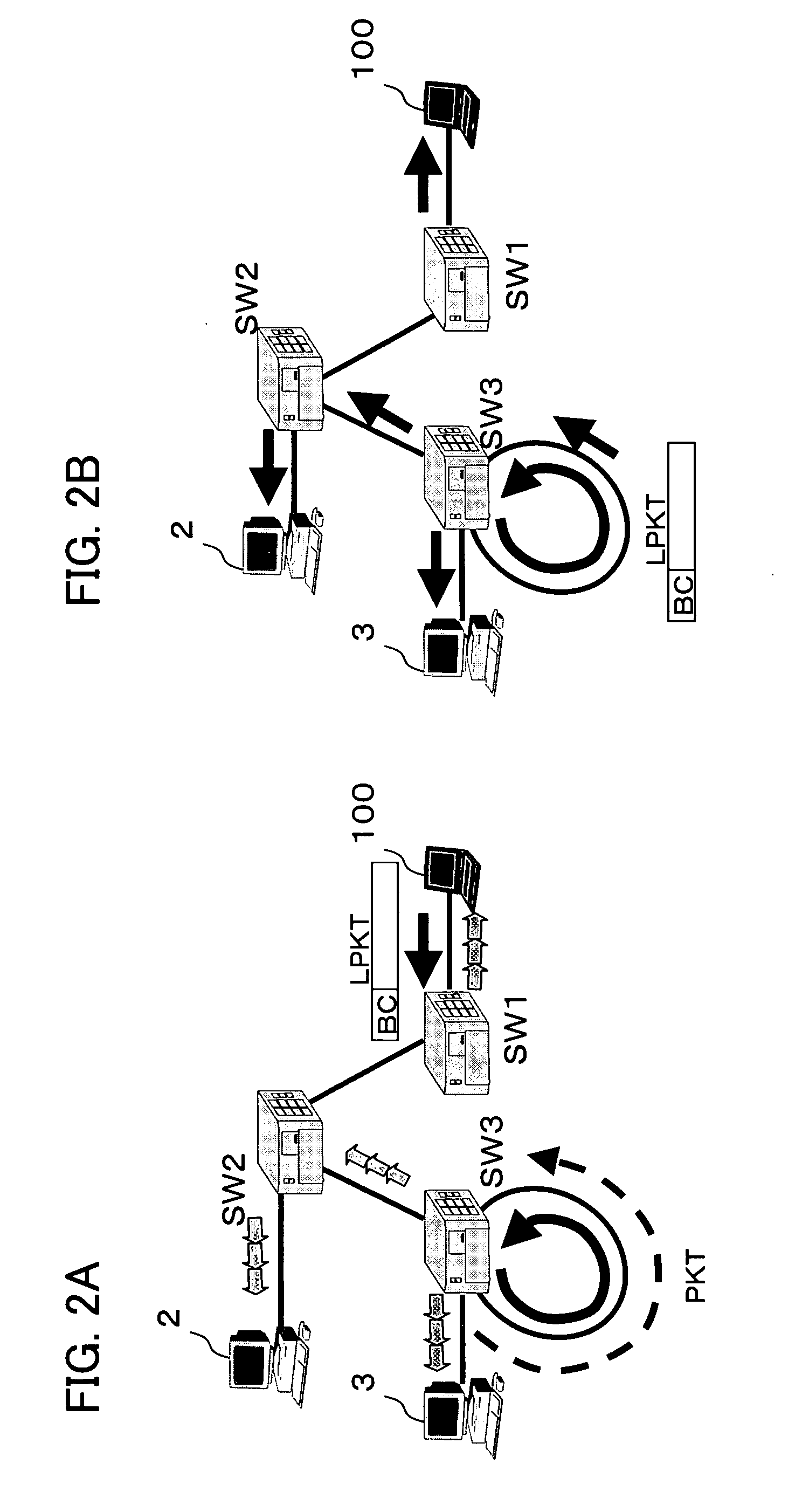
[0066] A third embodiment is characterized by having an advantage for preventing transmission of unwanted packets by controlling the number of transmitted long-size packets LPKT depending on a situation of the loop.

[0067]FIG. 8 is a process flow according to the third embodiment and FIG. 9 is a sequence flow showing a flow of signals. Typically, a plurality of packets is looped and the loop is sequentially started by broadcast packets PKT1, PKT2, . . . , PKTn transmitted by hosts 200A, 200B. At this point, the maximum number of the looped packet is depending on the number of packets which can be held by the loop switch LSW, i.e., a queue length of the switch.

[0068] In the principle of flushing out short packets by transmitting long-size packets, the short packet LPKT is intentionally discarded by generating a queue overflow at the loop switch LSW, and therefore, when the queue length is short, the queue overflow is easily generated even if the number of the transmitted long packet...


PUM


Abstract

In a communication system, transmission / reception of data can be performed between end hosts connected to a relay switch in a subnet even in an improper connection at a L2 level in the relay switch in a communication. Communication failure due to a packet loop generated by the improper connection of the L2 level is recovered by wherein the packet loop is stopped by continuously transmitting long-size MAC packets longer than a packet generating the packet loop into the subnet, which have destinations as a broadcast MAC address or multicast MAC address.

Description

CROSS-REFERENCE TO RELATED APPLICATIONS [0001] This application is based upon and claims the benefit of priority from the prior Japanese Patent Application No. 2005-172677, filed on Jun. 13, 2005, the entire contents of which are incorporated herein by reference. BACKGROUND OF THE INVENTION [0002] 1. Field of the Invention [0003] The present invention relates to a communication control method and a communication system to which the same is applied. More particularly, the invention relates to a communication control method for ensuring communication when a L2 loop is generated and a communication system to which the same is applied. [0004] 2. Description of the Related Art [0005] In network, a L2 loop (broadcast storm) is known as one of very frequent failures generated due to improper connections of LAN cables (see, e.g., Japanese Patent Application Laid-Open Publication No. 2002-252625). When the L2 loop is generated, not only higher loads are applied to transmission paths of an en...

Claims


Application Information

Patent Timeline
Patent Type & Authority Applications(United States)
IPC IPC(8): H04L12/28
CPCH04L12/462H04L69/324H04L69/40H04L12/4625
Inventor NOMURA, YUJIYASUIE, TAKESHI
Owner FUJITSU LTD
Why Eureka
Try Eureka