Loop-type heat exchange device

a heat exchange device and loop-type technology, applied in the direction of indirect heat exchangers, light and heating apparatuses, laminated elements, etc., can solve the problems of affecting workability and stability, affecting the workability of the heat exchange device, and the inability of known cooling devices such as heat sinks and cooling fans to remove heat from electronic components, etc., to achieve high heat-absorbing surface area, prevent an excessive amount of condensate, and enhance the heat exchange capability of the condenser

Inactive Publication Date: 2006-12-21
HON HAI PRECISION IND CO LTD
View PDF12 Cites 47 Cited by
  • Summary
  • Abstract
  • Description
  • Claims
  • Application Information

AI Technical Summary

Benefits of technology

[0010] Said means for exchanging heat with the vapor may be a plurality of heat-exchange pins extending in the chamber of the condenser. These heat-exchange pins function as a cooling-enhancing structure to enhance the heat exchange capability of the condenser. In one embodiment of the present heat exchange device, said means is a plurality of metal pin-fins. In an alternative embodiment, said means is a plurality of miniaturized heat-pipes. Thus, the condenser has a high heat-absorbing surface area due to the presence of these heat-exchange pins and accordingly the vapor entering into the condenser is capable of being effectively heat-exchanged with these heat-exchange pins.
[0011] As a further improvement, first and second wick structures are arranged inside the liquid conduit and the condenser respectively. The second wick structure connects with the first wick structure. Thus, the condensate in the condenser resulting from the vapor is capable of being timely sent back to the evaporator in a continuous manner under the capillary forces developed by the first and second wick structures, thereby preventing an excessive amount of the condensate from accumulating in the condenser and accordingly avoiding the potential dry-out problem occurring at the evaporator.

Problems solved by technology

As a result, the amount of heat generated by these electronic components during their normal operations is commensurately increased, which in turn will adversely affect their workability and stability.
However, currently well-known cooling devices such as heat sink plus cooling fan are no longer qualified or desirable for removing the heat from these electronic components due to their low heat removal capacity.
However, if the rotation speed of the cooling fan is increased, problems such as large noise will inevitably be raised.
On the other hand, by increasing the size of the heat sink, it will make the cooling device bulky, which contravenes the current trend towards miniaturization.
Heat pipes are an effective heat transfer means due to their low thermal resistance.
In the heat pipe, however, there still exists a fatal drawback awaited to be overcome.
If the condensate is not timely sent back to the evaporating section, the heat pipe will suffer a dry-out problem at that section.
However, the pipe section generally has a very limited circumferential surface area to contact with the fins and as a result, the interfacial resistance and the spreading resistance between the involved pipe section and the fins are relatively high.
As a result, the heat carried in the vapor cannot be effectively released since the vapor generally runs quickly in the heat transfer loop.
However, in this design, no effective mechanism is provided to ensure the condensate resulting from the vapor to return back to the evaporator rapidly and efficiently.
It is therefore easy to lead to the fact that a large amount of the condensate accumulates in the chamber of the condenser, and thus results in a dry-out problem at the evaporator as the condensate is not timely sent back thereto.

Method used


Image

  • Loop-type heat exchange device
  • Loop-type heat exchange device
  • Loop-type heat exchange device

Examples


first embodiment

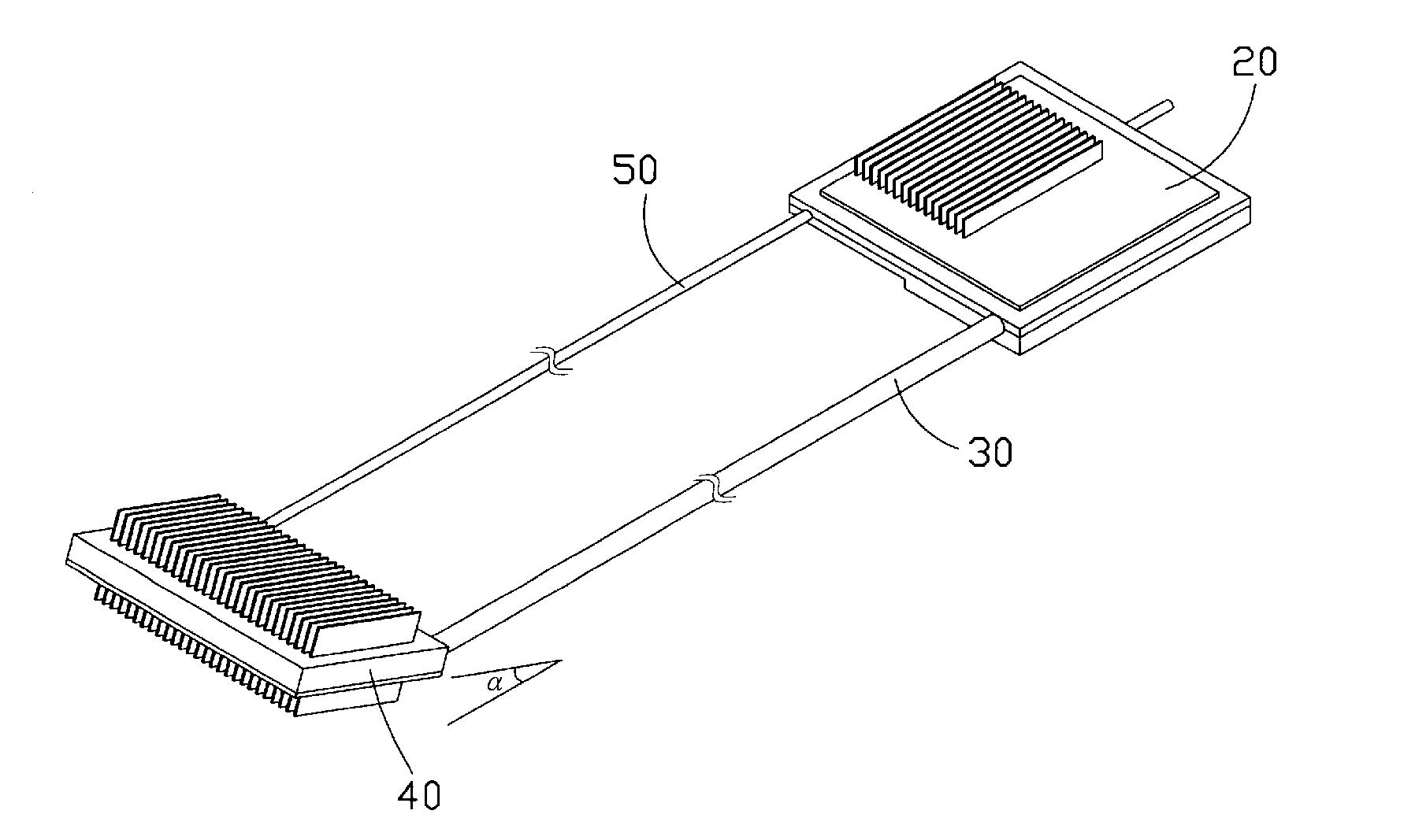
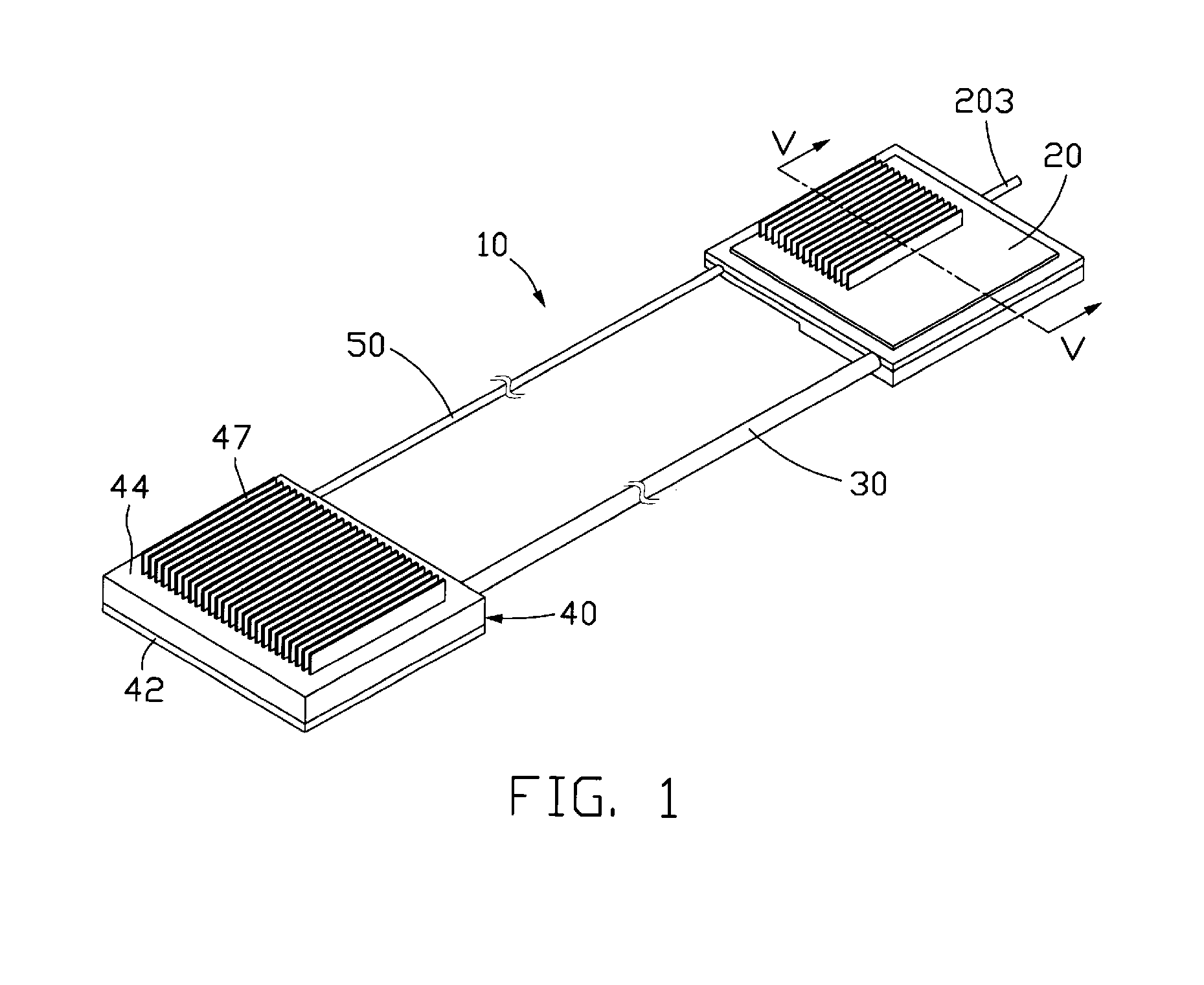
[0023]FIG. 1 illustrates a loop-type heat exchange device 10 in accordance with the present invention. The heat exchange device 10 includes an evaporator 20, a vapor conduit 30, a condenser 40 and a liquid conduit 50. The evaporator 20 preferably is made of two separable portions connected together, as will be discussed in more detail later. The vapor and liquid conduits 30, 50 lie in parallel to each other, although they are not limited to this relationship. Two ends of each of the vapor and liquid conduits 30, 50 are respectively connected to the evaporator 20 and the condenser 40. The vapor and liquid conduits 30, 50 preferably are made of flexible metal or non-metal materials so that they could be bent or flattened easily in order to cause the heat exchange device 10 to be applicable in electronic products having a limited mounting space such as notebook computers.

[0024] The heat exchange device 10 contains therein a working fluid (not shown). As heat from a heat source (not sho...

second embodiment

[0034]FIG. 8 shows a loop-type heat exchange device (not labeled) in accordance with the present invention. In this embodiment, the condenser 40 is disposed aslant with respect to the liquid conduit 50 and the vapor conduit 30, with an acute angle (a) formed therebetween. Thus, the condensate is capable of entering from the condenser 40 into the liquid conduit 50 more easily due to an additional driving force, i.e., the gravity of the condensate. In this embodiment, the condenser 40 is located at a position higher than that of the evaporator 20.

third embodiment

[0035]FIG. 9 shows a loop-type heat exchange device (not labeled) in accordance with the present invention. In this embodiment, the condenser 40 is disposed perpendicularly to the liquid conduit 50 and the vapor conduit 30. This heat exchange device is suitable for use in a desktop computer or the like and the heat removal capacity of the condenser 40 can be further improved by employing the forced airflow coming from the system cooling fan installed on the desktop computer. In this embodiment, the condenser 40 is located at a position higher than that of the evaporator 20.


PUM


Abstract

A loop-type heat exchange device (10) is disclosed, which includes an evaporator (20), a condenser (40), a vapor conduit (30) and a liquid conduit (50). The evaporator contains therein a working fluid. The working fluid in the evaporator evaporates into vapor after absorbing heat, and the generated vapor flows, via the vapor conduit, to the condenser where the vapor releases its latent heat of evaporation and is condensed into condensate. The condensate then returns back, via the liquid conduit, to the evaporator to thereby form a heat transfer loop. The condenser defines therein a chamber, and a plurality of heat-exchange pins is provided inside the chamber for effectively exchanging heat with the vapor entering into the condenser.

Description

FIELD OF THE INVENTION [0001] The present invention relates generally to an apparatus for transfer or dissipation of heat from heat-generating components, and more particularly to a loop-type heat exchange device suitable for removing heat from electronic components. DESCRIPTION OF RELATED ART [0002] As progress continues to be made in electronic industries, electronic components such as integrated circuit chips are produced to have more powerful functions while maintaining a unchanged size or even a smaller size. As a result, the amount of heat generated by these electronic components during their normal operations is commensurately increased, which in turn will adversely affect their workability and stability. It is well known that cooling devices are commonly used to remove heat from heat-generating components. However, currently well-known cooling devices such as heat sink plus cooling fan are no longer qualified or desirable for removing the heat from these electronic component...

Claims


Application Information

Patent Timeline
Patent Type & Authority Applications(United States)
IPC IPC(8): F28D15/04
CPCF28D15/043F28D15/046F28D2015/0216F28F3/02F28F2210/02H01L2924/0002F28D15/0266H01L2924/00
Inventor LIU, TAY-JIANTUNG, CHAO-NIENLEE, CHIH-PENGHOU, CHUEN-SHUYANG, CHIH-HAO
Owner HON HAI PRECISION IND CO LTD
Why Eureka
Try Eureka