Hydrofoil for an amphibious aircraft

a technology for amphibious aircraft and hydrocarbons, which is applied in the direction of propellers, seaplanes, transportation and packaging, etc., can solve the problems of reducing the range and airspeed of aircraft, degrading the maneuverability of aircraft, and affecting the efficiency of power plants, so as to improve the displacement of aircraft and improve the effect of power plant efficiency

Inactive Publication Date: 2006-12-21
LEADER INDS
View PDF17 Cites 24 Cited by
  • Summary
  • Abstract
  • Description
  • Claims
  • Application Information

AI Technical Summary

Benefits of technology

[0020] In another aspect of an embodiment of the invention, the invention can include a general aviation class aircraft adapted to land and take off on water. The aircraft can include at least one fuselage with a cantilevered lifting surface, the at least one fuselage containing a cockpit and hydrodynamic fairing, the at least one fuselage capable of floating the aircraft on water in order to allow take off, taxiing and landing operations. Further, the aircraft can include a power plant mounted to the at least one fuselage, the power plant located adjacent to a portion of the fuselage and conne

Problems solved by technology

These and other considerations often caused tradeoffs between flotation and hydrodynamic performance.
Pontoons or floats were added to conventional hull designs which created additional aerodynamic drag, which reduced range and airspeed as well as creating

Method used


Image

  • Hydrofoil for an amphibious aircraft
  • Hydrofoil for an amphibious aircraft
  • Hydrofoil for an amphibious aircraft

Examples


Embodiment Construction

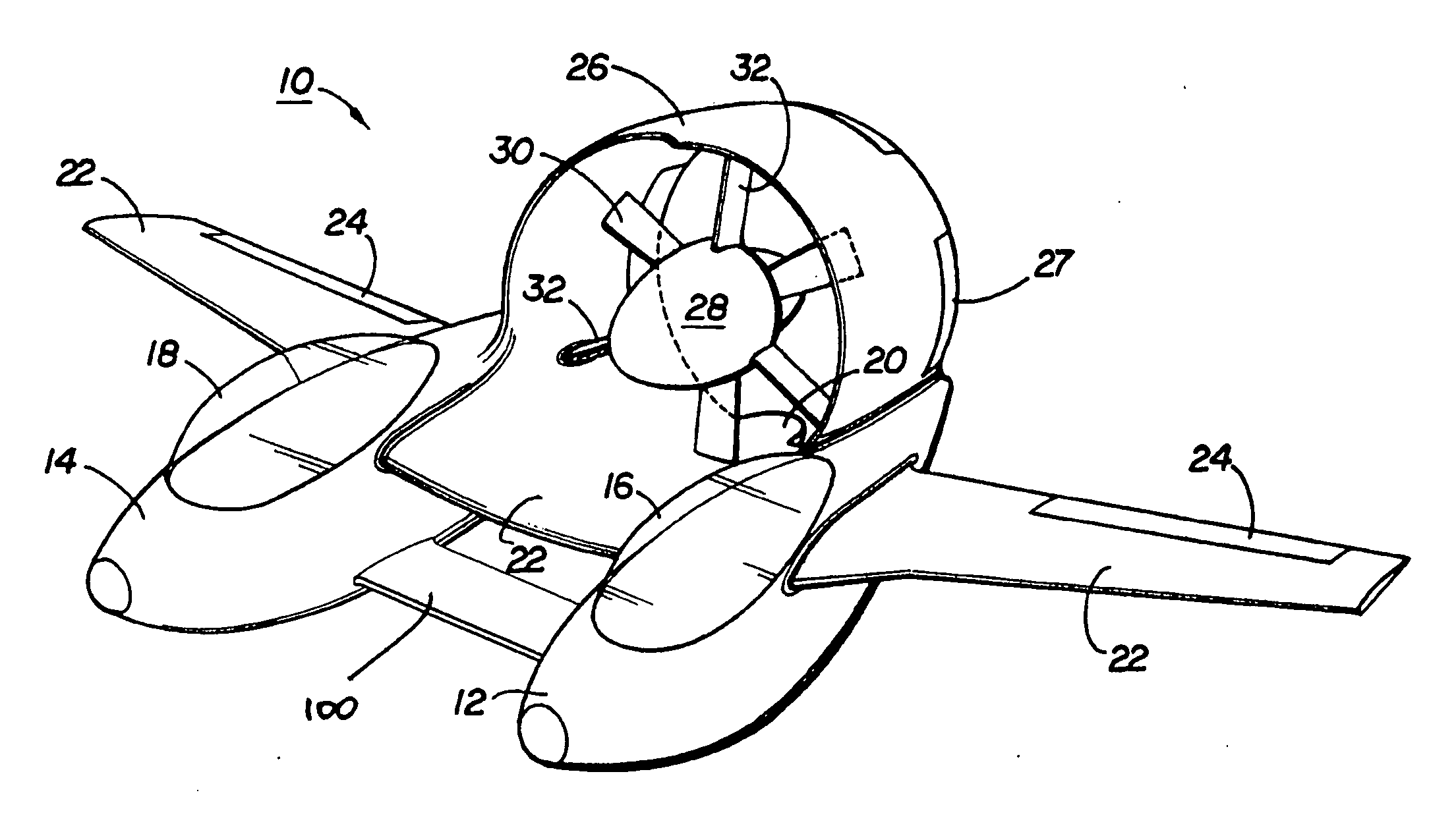
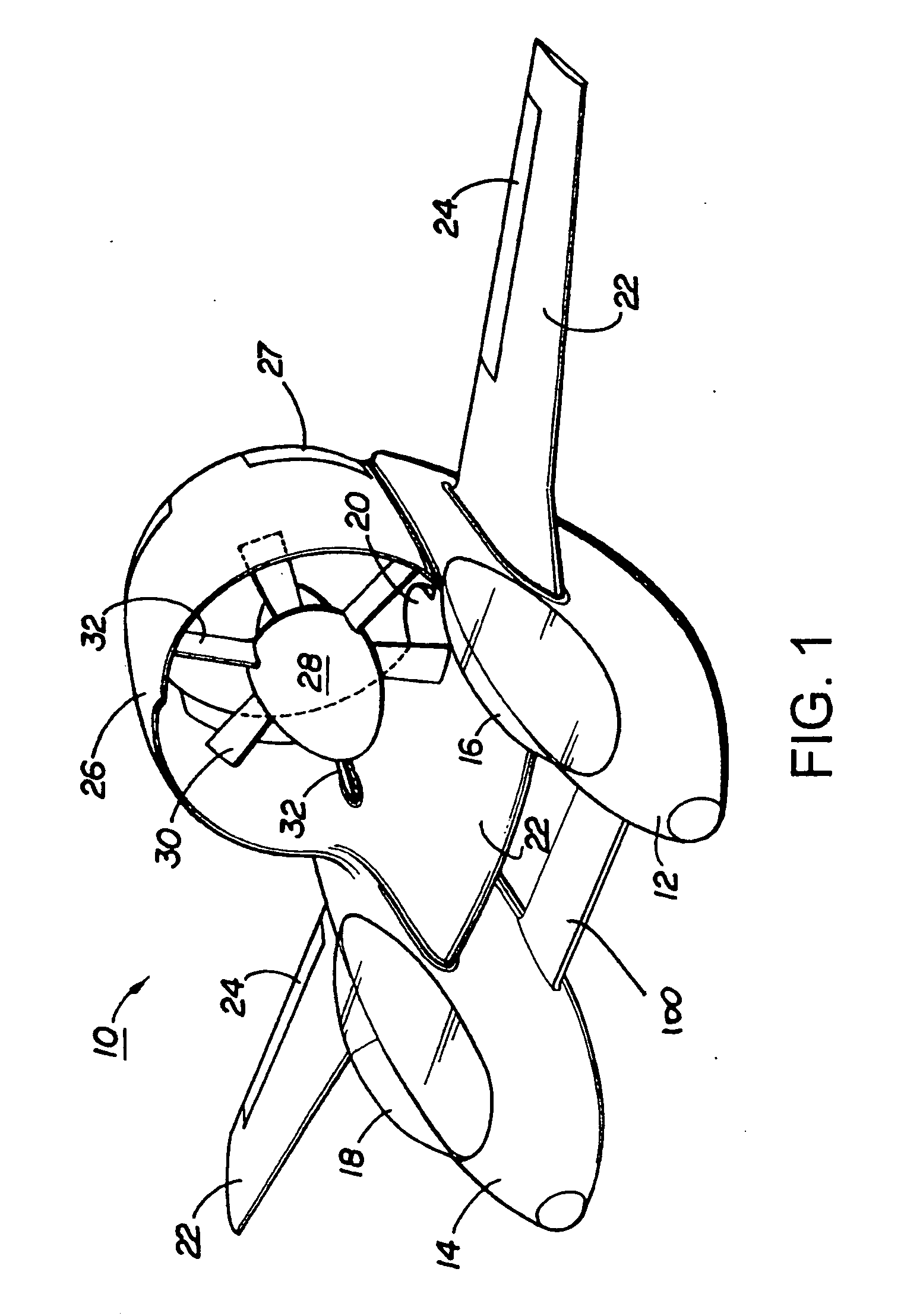
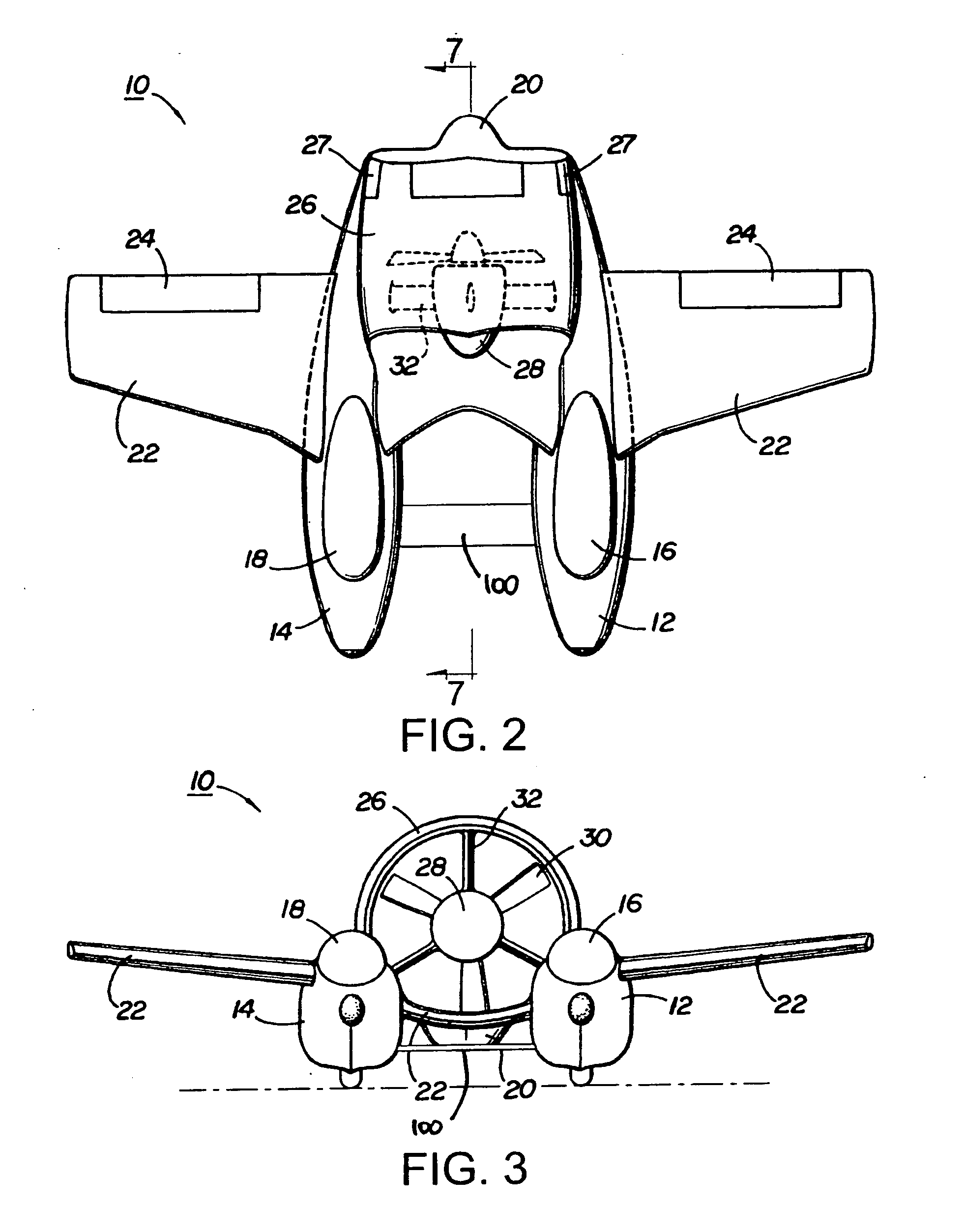
[0040]FIGS. 1-7 all show one preferred embodiment of an amphibious aircraft with a hydrofoil according to a preferred embodiment of the present invention. FIG. 8 shows another preferred embodiment of an amphibious aircraft with a hydrofoil according to a preferred embodiment of the present invention. FIGS. 9 and 10 show methods of use of an amphibious aircraft with a hydrofoil according to embodiments of the invention.

[0041] The embodiment shown in FIGS. 1-7 features a hydrofoil 100, or other control apparatus, mounted to a twin fuselage, twin hull seaplane or amphibious aircraft 10. The hydrofoil 100 is capable of reducing drag and increasing lift of the amphibious aircraft during takeoffs and landings. Moreover, the hydrofoil is capable of increasing stability, maneuverability, and control of the amphibious aircraft during takeoffs and landings. Furthermore, the hydrofoil 100 is capable of providing additional displacement for the amphibious aircraft during landings. In this embo...


PUM


Abstract

A control apparatus, such as a hydrofoil, for general aviation class amphibious aircraft which include at least one fuselage having a hydrodynamic surface, the fuselage including a primary flight surface and a ducted power plant located aft and above the fuselage. The power plant location removes the fan/propeller arc from water and spray during water-borne taxiing, takeoff and landing. The combination of the hydrofoil, fuselage, lifting surface and ducting provides an aerodynamically efficient design with a lower center of gravity and protected powerplant for yielding improved performance including increased range and airspeed, together with favorable maneuverability, stability and control characteristics both aerodynamically and hydrodynamically.

Description

TECHNICAL FIELD [0001] The invention relates to amphibious aircraft, and more particularly to, a hydrofoil for an amphibious aircraft. BACKGROUND [0002] Conventional hulls for seaplanes or amphibious aircraft evolved based in part on the need for amphibious aircraft to operate in the water at a variety of speeds, ranging from an initial takeoff to take-off speeds, and from landing speeds to final landing. Such hull designs sought to reduce the amount of drag while the hull was in contact with the water, and further, to generate lift when a sufficient portion of the hull was out of contact with the water. Moreover, conventional hull designs also accounted for the necessary displacement to support the weight of the amphibious aircraft while in the water. These and other considerations often caused tradeoffs between flotation and hydrodynamic performance. [0003] Initial attempts to address performance aspects of amphibious aircraft hull design focused on improvements to either increase...

Claims


Application Information

Patent Timeline
IPC IPC(8): B64C35/00
CPCB64C11/001B64C35/006Y02T50/66B64C39/04B64C35/008Y02T50/60
Inventor MEEKINS, JOHN A.
Owner LEADER INDS
Why Eureka
Try Eureka