
Charging mode control circuit and method

a control circuit and charging mode technology, applied in electric vehicles, electric power, transportation and packaging, etc., can solve the problems of portable devices not being able to communicate with computers, the current of charging is rather small, and the charging speed is rather slow

Inactive Publication Date: 2006-12-21
HON HAI PRECISION IND CO LTD
View PDF4 Cites 103 Cited by
  • Summary
  • Abstract
  • Description
  • Claims
  • Application Information

AI Technical Summary

Benefits of technology

[0010] Based on the present invention, the secondary battery can be charged in a fast-charging mode by inserting the commutator which include the AC / DC adapter therein between the computer and the portable device. The AC / DC adapter provides a relative large current for the charging mode control circuit, which make it feasible to charge the secondary battery fixed within the portable device quickly during data transmission with an external computer.

Problems solved by technology

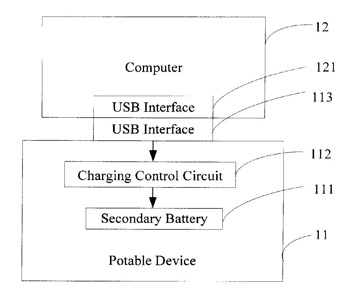
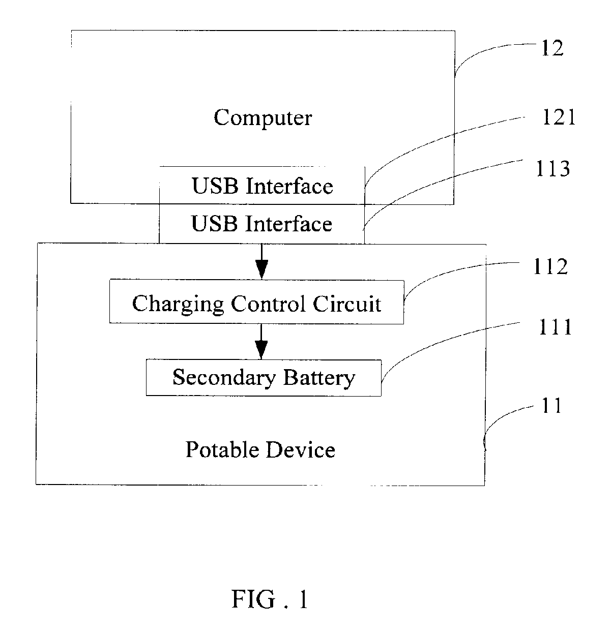
Given these circumstances, a secondary battery 11 fixed within the portable device 11 can obtain a charging current from the computer 12 while in-link with the computer, however this charging current is rather small and the charging speed is rather slow.
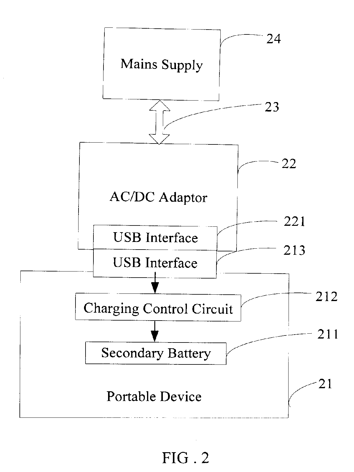
Using such charging means, a secondary battery 211 fixed within the portable device 21 can obtain a fairly bigger current resulting to a quicker charging speed, however, the portable device will not be able to communicate with a computer while the battery 211 is charging.

Method used


Image

  • Charging mode control circuit and method
  • Charging mode control circuit and method
  • Charging mode control circuit and method

Examples


Embodiment Construction

[0015]FIG. 3 is a block diagram of an exemplary application of a charging mode control circuit and method in accordance with a preferred embodiment of the present invention. Shown here are a portable device 31, a commutator 32, and a computer 33. The portable device 31 has a charging mode control circuit 312 incorporated therein and a secondary battery 311 fixed therein. The charging mode control circuit 312 is used to select a selective charging mode on the secondary battery 311 according to a particular charging power supply available.

[0016] The commutator 32 includes an adapter 323 and two USB interfaces 321 and 322. The USB interface 321 is connected directly to the USB interface 313 of the portable device 31 and the USB interface 322 is connected directly to the USB interface 322 of the computer 33. Each of the USB interfaces 321 and 322 has a VCC (power) pin, a GND (ground) pin, and a plurality of DATA (data) pins. The AC / DC adapter 323 has a VCC line and a GND line. The VCC ...


PUM


Abstract

The present invention provides a charging mode control circuit and method. By utilizing such charging mode control circuit and method, a secondary battery fixed in a portable device can be quickly charged when the portable device communicate with an external computer. The method includes the steps of:a) providing a commutator, the commutator comprising an AC / DC adapter, a first interface, and a second interface, wherein the first interface is connected to the external computer and the second interface is connected to the portable device; b) comparing a charging voltage with a reference voltage, thereby producing a high voltage level signal according to a comparison result, wherein the charging voltage come from the AC / DC adapter; and c) selecting a fast-charging mode on the secondary battery according to the high voltage level signal.

Description

TECHNICAL FIELD [0001] The present invention relates to a charging mode control circuit and method, particularly to a charging mode control circuit and method used in a portable device. GENERAL BACKGROUND [0002] Portable devices with Universal Serial Bus (USB) interfaces such as portable computers are welcomed by users for their small size and convenient usage. At present there are generally two solutions for charging a secondary battery equipped in a portable device. [0003] One of the solution is shown in FIG.1 where a portable device 11 is connected with a computer 12 via their USB interfaces (i.e., USB interface 113 and USB interface 121). According to the protocol standards of USB 1.1 and USB 2.0, the maximum power transmitted by USB interfaces is 2.5 watt (0.5A @ 5V), in other words, the computer supplies no more than 500 mA charging current under the charging voltage of +5V. Given these circumstances, a secondary battery 11 fixed within the portable device 11 can obtain a char...

Claims


Application Information

Patent Timeline
Patent Type & Authority Applications(United States)
IPC IPC(8): H02J7/00
CPCH02J2007/006H02J7/0077H02J2207/30H02J7/00712
Inventor HSIEH, KUAN-HONGWANG, HAN-CHECHUNG, SHIN-HONG
Owner HON HAI PRECISION IND CO LTD
Learn More