Fly's-eye lens sheet having light-shielding layer, method for fabricating the same, transmissive screen, and rear projection image display device

a technology of light shielding layer and lens, which is applied in the field of flying lens sheet having a light shielding layer, can solve the problems of loss of adhesion, reduced image light intensity, and reduced image quality, and achieves good transmittance, large area ratio, and high contrast ratio of display image

Inactive Publication Date: 2006-12-21
SONY CORP
View PDF6 Cites 23 Cited by
  • Summary
  • Abstract
  • Description
  • Claims
  • Application Information

AI Technical Summary

Benefits of technology

[0022] As described above, according to the embodiment of the present invention, it is possible to obtain a transmissive screen having a

Problems solved by technology

In such image display devices, external light, such as fluorescent light, present on the side of the viewer is reflected from the display surfaces of the image display devices, resultin

Method used


Image

  • Fly's-eye lens sheet having light-shielding layer, method for fabricating the same, transmissive screen, and rear projection image display device
  • Fly's-eye lens sheet having light-shielding layer, method for fabricating the same, transmissive screen, and rear projection image display device
  • Fly's-eye lens sheet having light-shielding layer, method for fabricating the same, transmissive screen, and rear projection image display device

Examples


first embodiment

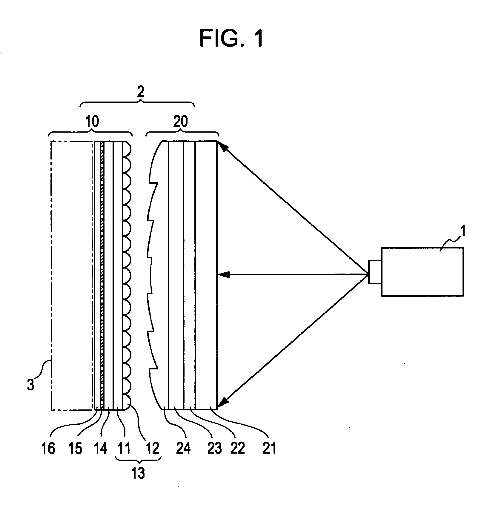
[0048] [Overall Structure of Rear Projection Image Display Device]

[0049]FIG. 1 is a schematic diagram showing an example of a structure of a rear projection image display device according to a first embodiment of the present invention. This rear projection image display device includes a projector 1 and a transmissive screen 2, and an image projected from the projector 1 is transmitted through the transmissive screen 2 for display.

[0050] The projector 1 enlarges and projects an image on the transmissive screen 2. As the projector 1, for example, a projector in which liquid crystal display elements or digital light processing “DLP (Registered Trademark)” elements are used as light valves may be used. As the projector 1 provided with liquid crystal display elements, for example, a projector provided with transmissive liquid crystal display elements or reflective liquid crystal display elements may be used. The transmissive screen 2 displays an image projected by the projector 1.

[005...

second embodiment

[0129] A second embodiment of the present invention will now be described.

[0130] In the first embodiment, the case in which a planar workpiece is subjected to laser-beam machining to form a mold has been described. In the second embodiment, the case in which a cylindrical workpiece is subjected to laser-beam machining to form a mold will be described.

[0131] The second embodiment is the same as the first embodiment except for the method for fabricating a fly's-eye lens sheet having a light-shielding layer. A method for fabricating a fly's-eye lens sheet having a light-shielding layer will be described below.

[0132] The method for fabricating the fly's-eye lens sheet having the light-shielding layer according to the second embodiment will be described in the following order:

[0133] (1) Formation of mold

[0134] (2) Formation of duplicate mold

[0135] (3) Formation of sheet body

[0136] (4) Formation of light-shielding layer

[0137] (1) Formation of Mold

[0138] First, a cylindrical workp...

third embodiment

[0159]FIG. 20 is a schematic diagram showing an example of a structure of a rear projection image display device according to a third embodiment of the present invention. The same reference numeral is attached to each corresponding part to that employed in the first embodiment, and detailed description thereof is omitted.

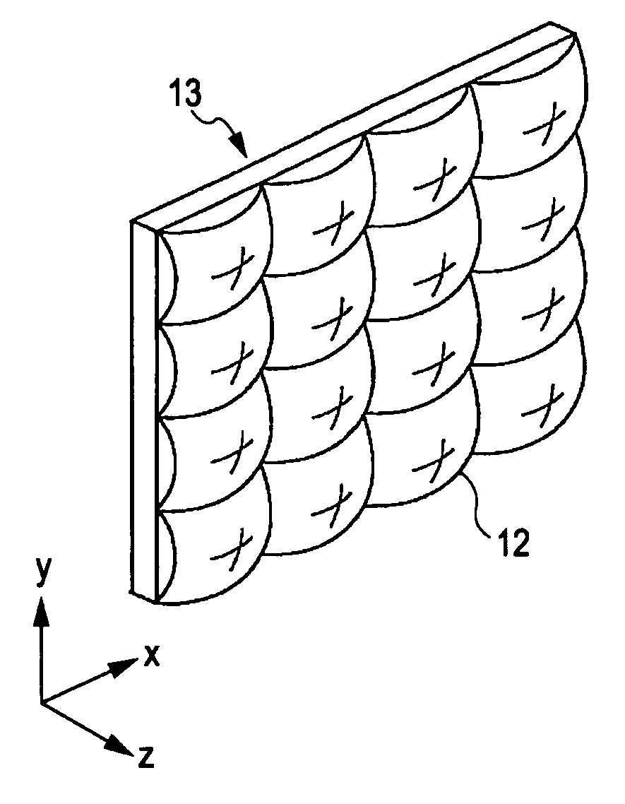
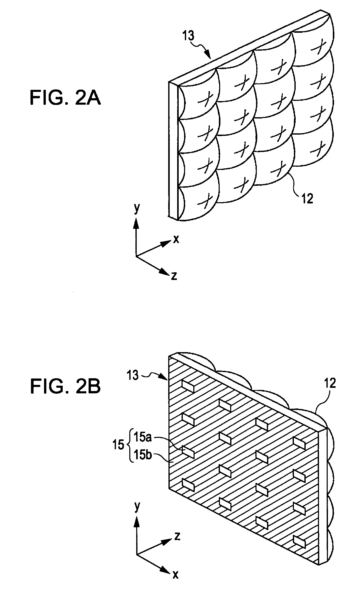
[0160] In this embodiment, a fly's-eye lens sheet having a light-shielding layer 10 includes a fly's-eye lens sheet body 13 provided with fly's-eye lenses 12 on one principal surface thereof, a light-shielding layer 15 disposed on the other principal surface of the fly's-eye lens sheet body 13, and a photosensitive adhesive layer 14 disposed between the fly's-eye lens sheet body 13 and the light-shielding layer 15.

[0161] The photosensitive adhesive layer 14 has adhesive and non-adhesive patterns as in the first embodiment. The light-shielding layer 15 includes a light-shielding portion 15b disposed on an adhesive pattern of the photosensitive adhesive layer 14, an...


PUM


Abstract

A fly's-eye lens sheet having a light-shielding layer includes a fly's-eye lens sheet body provided with fly's-eye lenses on one principal surface thereof, the light-shielding layer provided on the other principal surface of the fly's-eye lens sheet body, and a photosensitive adhesive layer disposed between the fly's-eye lens sheet body and the light-shielding layer, the photosensitive adhesive layer having adhesive and non-adhesive patterns, wherein the light-shielding layer includes a light-shielding portion disposed on the adhesive pattern and transmitting portions disposed on the non-adhesive pattern for transmitting light transmitted through the fly's-eye lenses, the transmitting portions are located at positions corresponding to light-collecting parts of the fly's-eye lenses, and the light-shielding portion contains carbon particles, the content of the carbon particles being 45% to 65% by weight.

Description

CROSS REFERENCES TO RELATED APPLICATIONS [0001] The present invention contains subject matter related to Japanese Patent Application JP 2005-164857 filed on Jun. 3, 2005, Japanese Patent Application JP 2005-164858 filed on Jun. 3, 2005, and Japanese Patent Application JP 2006-146908 filed on May 26, 2006, in the Japanese Patent Office, the entire contents of which are incorporated herein by reference. BACKGROUND OF THE INVENTION [0002] 1. Field of the Invention [0003] The present invention relates to a fly's-eye lens sheet having a light-shielding layer, the fly's-eye lens sheet including a fly's-eye lens sheet body, fly's-eye lenses disposed on one principal surface thereof, and the light-shielding layer disposed on the other principal surface thereof; a method for fabricating the fly's-eye lens sheet; a transmissive screen; and a rear projection image display device. [0004] 2. Description of the Related Art [0005] Image display devices in which transmitted light from light sources...

Claims


Application Information

Patent Timeline
IPC IPC(8): G02B27/10B29D11/00G02B5/02G03B21/62
CPCB29D11/00278G03B21/625G02B3/0056G02B3/0031G02B3/0025G02B3/005
Inventor HAGA, YUMIMIYAKI, YUKIOKISO, HIROYUKINAGAHAMA, TSUTOMUMATSUMURA, SHINICHI
Owner SONY CORP
Why Eureka
Try Eureka