Fuel cell system with consumption-optimizing unit

a fuel cell and consumption-optimizing technology, applied in the field of fuel cell systems with consumption-optimizing units, can solve the problem that the quantity of fuel stored in the fuel tank will fall below the minimum quantity, and achieve the effect of reducing the amount of energy consumed, saving fuel, and increasing the fuel efficiency of the motor vehicl

Inactive Publication Date: 2006-12-21
ROBERT BOSCH GMBH
View PDF5 Cites 12 Cited by
  • Summary
  • Abstract
  • Description
  • Claims
  • Application Information

AI Technical Summary

Benefits of technology

[0010] It is advantageous, in particular, when the consumer unit can be operated in different operating modes to fulfill its primary task.
[0015] To reduce the amount of energy consumed by the consumption unit, it is possible for the consumption-optimizing unit, in a further step, to switch to a different operating mode, and if necessary, to change the availability of the vehicle propulsion to limited or even minimum functionality, in order to increase the fuel efficiency of the motor vehicle that can be obtained from the remaining quantity of fuel.
[0016] A further possibility would be to integrate available intermediate energy accumulators in the drive of the consumers, so that a portion of the operation of the fuel cell can be temporarily reduced or even interrupted entirely, in order to save more fuel. Another possibility, therefore, is to forfeit a portion of the dynamics of vehicular operation as a secondary property of the drive system instead of increasing fuel efficiency, in order to reach a refueling station.
[0017] To support the primary requirement on the fuel cell system, i.e., to increase the distance to empty of the motor vehicle, it is also considered advantageous for the consumption-optimizing unit to interact with a navigation system. This makes it possible to display the location of refueling stations to the operator, so he can drive to a refueling station, fill the tank, and avoid having the motor vehicle come to a standstill. Other types of optimizations based on the driving route, distance and traffic conditions are possible, of course.

Problems solved by technology

During operation of a fuel cell system it cannot be ruled out, however, that the quantity of fuel stored in the fuel tank will fall below a minimum quantity required to operate the consumer supplied with energy by the fuel cell.

Method used


Image

  • Fuel cell system with consumption-optimizing unit
  • Fuel cell system with consumption-optimizing unit

Examples


Embodiment Construction

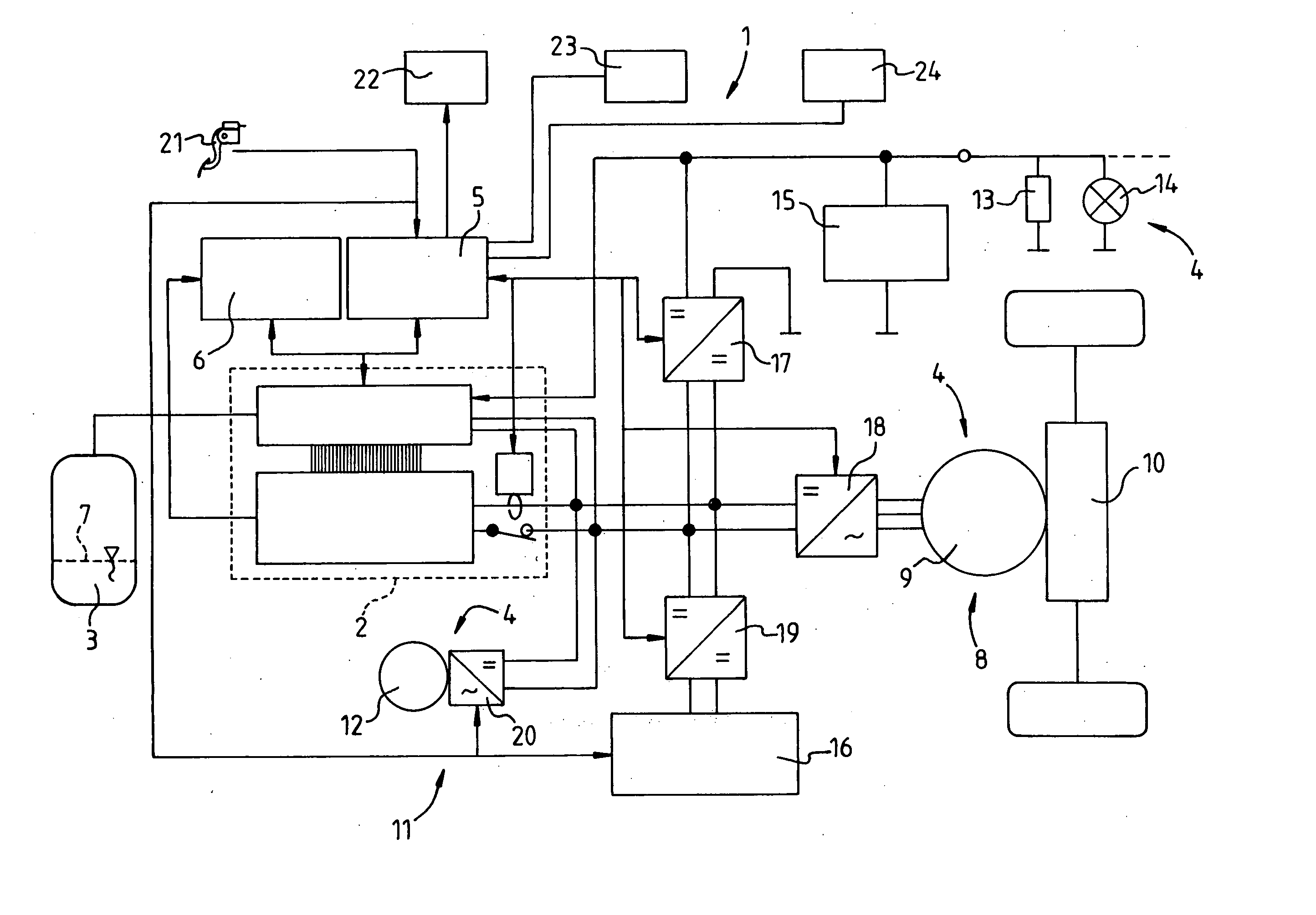
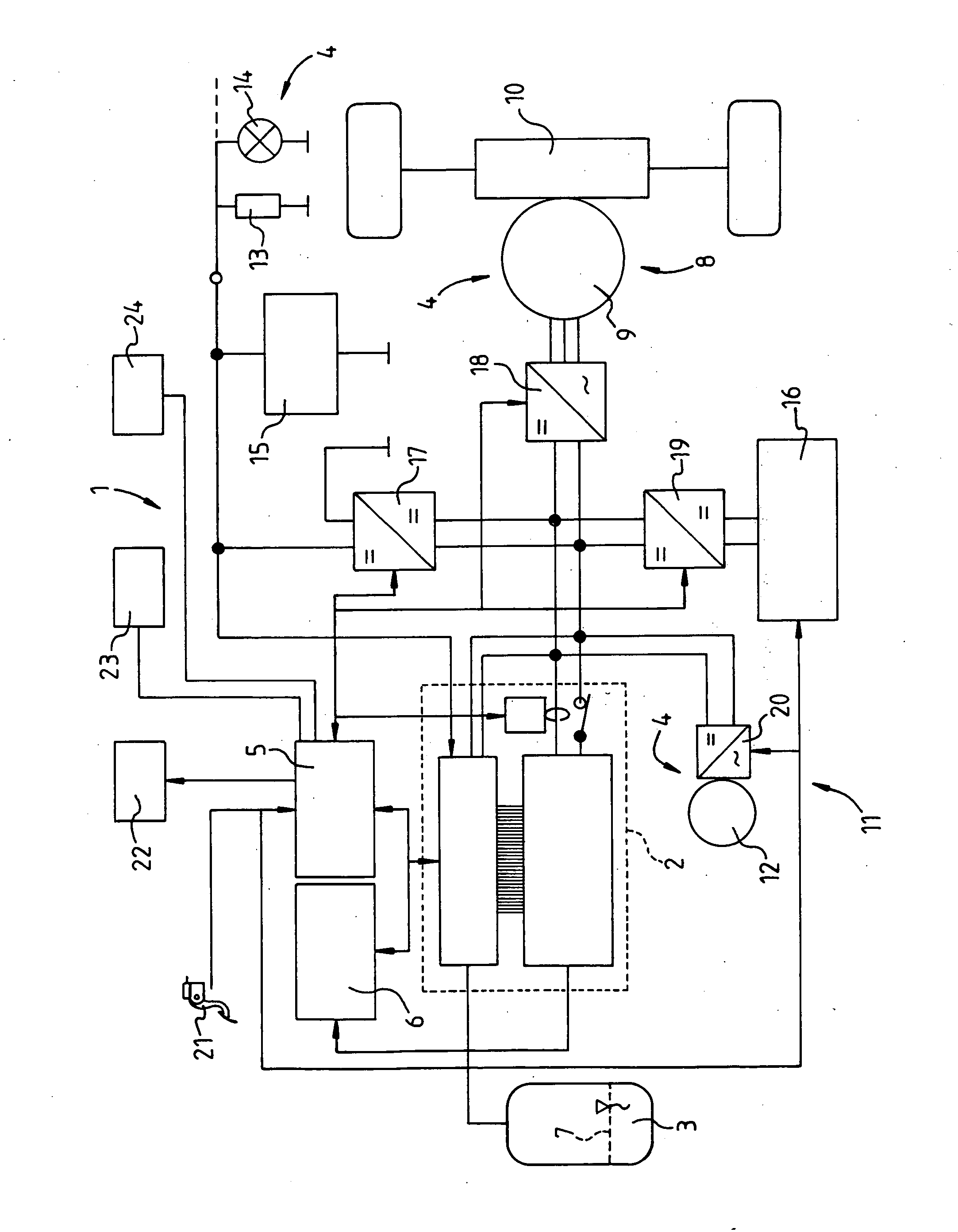
[0022] The fuel cell system is a consumption-optimizing unit in accordance with the present invention is shown in the drawings.

[0023] The fuel cell system is identified with reference numeral 1. The fuel cell system includes a fuel cell 2, a fuel cell tank 3, and a consumer unit 4.

[0024] According to the present invention, this fuel cell system 1 is equipped with a consumption-optimizing unit 5 that monitors fill level 7 of fuel tank 3 in order to monitor the energy demand and / or energy supply to consumer unit 4, which can be operated in different operating modes. In one or more of these operating modes, consumption-optimizing unit 5 is capable of limiting and even interrupting, if necessary, the energy supply to one or more consumers 8, 11, 13, 14 of consumer unit 4 as a function of fill level 7 of fuel tank 3.

[0025] With mobile fuel cell system 1 shown here as an example, the consumers (Vx)—which are also presented as examples—are consumer 8, which is the drive of the motor veh...


PUM

PropertyMeasurementUnit
energyaaaaaaaaaa
pressureaaaaaaaaaa
temperatureaaaaaaaaaa

Abstract

A fuel cell system which including a fuel cell, a fuel tank and a consumer unit, to improve the operation of a fuel cell, is equipped with a consumption-optimizing unit that limits or interrupts the energy supply to one or more consumers of the consumer unit depending on the fill level of the fuel tank in order to ensure at least the basic function of the fuel cell system for as long as possible.

Description

CROSS-REFERENCE TO A RELATED APPLIACTION [0001] The invention described and claimed hereinbelow is also described in German Patent Application DE 102005027651.2 filed on Jun. 15, 2005. This German Patent Application, whose subject matter is incorporated here by reference, provides the basis for a claim of priority of invention under 35 U.S.C. 119(a)-(d). BACKGROUND OF THE INVENTION [0002] The present invention relates to a fuel cell system with consumption-optimizing unit. [0003] Fuel cell systems for stationary and mobile use are becoming increasingly important. In terms of utilizing the consumers operated by the fuel cell systems, a decisive factor is the presence of a sufficient quantity of fuel, which is preferably stored in a fuel tank assigned to the fuel cell system. [0004] The fill level of a gas tank filled under high pressure, as is the case, e.g., with a fuel tank for storing fuel for a fuel cell system, can be determined very exactly and displayed by using Van der Waals ...

Claims


Application Information

Patent Timeline
Patent Type & Authority Applications(United States)
IPC IPC(8): H01M8/04
CPCH01M8/04313H01M8/0432Y02T90/32H01M2250/20Y02E60/50H01M8/0438Y02T90/40
Inventor BINDER, JUERGENGOTTWICK, ULRICHSCHAEFERT, ARTHUR
Owner ROBERT BOSCH GMBH
Why Eureka
Try Eureka