
Long-term secure digital signatures

a digital signature and long-term technology, applied in the field of long-term secure digital signatures, can solve the problems of limited computational power, inability to fulfill, document security, etc., and achieve the effect of less computationally intensive key revocation, simplified revocation process and convenient key revocation

Inactive Publication Date: 2006-12-21
IBM CORP
View PDF3 Cites 77 Cited by
  • Summary
  • Abstract
  • Description
  • Claims
  • Application Information

AI Technical Summary

Benefits of technology

[0014] In general, the invention solves the problem of creating digital signatures that must be secure for a very long time, taking into account future cryptographic developments which could render current cryptographic key-lengths insufficient. Having a digital signature or part thereof calculated on an easy transportable device, such as a smart card, makes a user legally liable for documents that he / she digitally signs. In accordance with the invention a double signature is issued for each document, one ensuring the long time security, the other one ensuring the involvement of the individual user. The final signature of the document is therefore a combination of these two signatures. Taking into account the nature of the two signatures in terms of used key size and of the calculation algorithms, it seems not to be useful to regenerate the signatures during the life of a document. The combination of these two signatures allows a very high security level, for short tern and overall for long term.

Problems solved by technology

However, at present the requirement that a user is legally liable for documents that he / she digitally signs and that the documents remain secure for a long period of time, for example at least 30 years, can not be fulfilled, because of the limited computational power of personal cryptographic tokens.
It should not be possible to create any signature without the users consent.
Current hardware tokens of this type are restricted in terms of computational power which means that digital signatures with very large key lengths cannot be computed within an acceptable time.

Method used


Image

  • Long-term secure digital signatures
  • Long-term secure digital signatures
  • Long-term secure digital signatures

Examples


Embodiment Construction

[0032] In the following, the various exemplary embodiments of the invention are described.

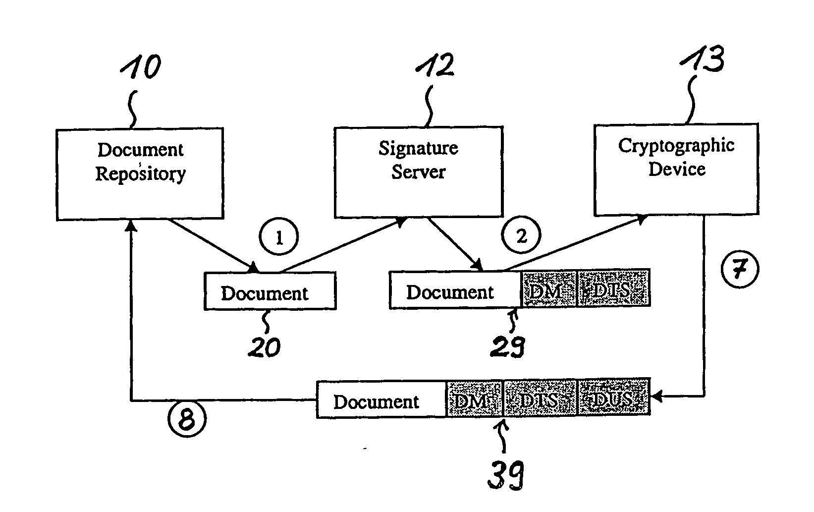
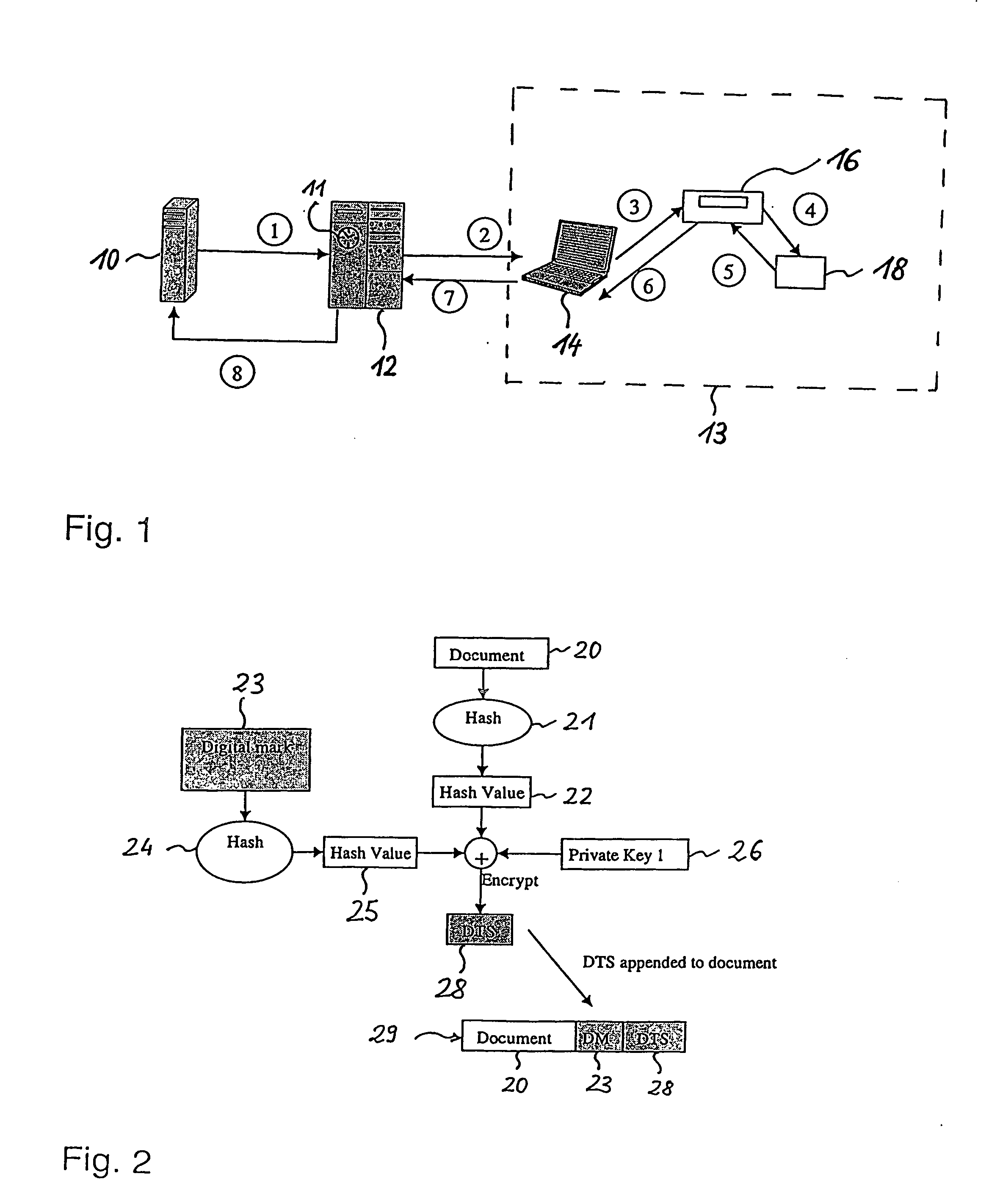
[0033]FIG. 1 shows a schematic illustration of units within a system for digitally signing and verifying an electronic document that is to be kept secure for many years. A document repository 10, which can be a database server, stores electronic documents. The document repository 10 is connected to a digital signature computing device 12 that is contemplated as a digital signature server or time-stamping server, hereafter also referred to as signature server 12. This server is regarded as a highly secure server with an accurate tamperproof clock 11. A cryptographic device 13 is connected to the signature server 12 usually via a network. In-between might be an application server located (not shown) for forwarding of requests. The cryptographic device 13 comprises a computer device 14, which here is a client computer 14, a card or smart card reader 16, and a smart card 18 which operates together...


PUM


Abstract

The present invention relates to digitally signing of electronic documents which are to be kept secure for a very long time, thereby taking into account future cryptographic developments which could render current cryptographic key-lengths insufficient. In accordance with the invention a double signature is issued for each document. A first digital signature (DTS) ensures the long time security, whilst a second digital signature (DUS) ensures the involvement of an individual user. Thereby, the second digital signature is less computationally intensive in its generation than the first digital signature.

Description

TECHNICAL FIELD [0001] The present invention is related to a method, computer device, and system for digitally signing an electronic document that is to be kept secure for a long time period. The invention also relates to a method for verifying an electronic document that has been digitally signed. BACKGROUND OF THE INVENTION [0002] More and more documents are stored electronically. This often involves a digital time-stamping mechanism in order to bind the document or its content to a particular point in time. To minimize the risk that either the data or the time-stamp can be tampered with at a later date a cryptographic digital signature is used to protect both elements. [0003] US Patent Application Publication US 2002 / 0120851 A1 refers to a device and method for data time-stamping. The device includes a trusted clock, a memory, a time-stamper and a digital signer. The device is adapted to store to the memory data that has been time-stamped by the time-stamper, with a time obtained...

Claims


Application Information

Patent Timeline
IPC IPC(8): H04L9/00H04L9/32
CPCH04L9/3234H04L2209/60H04L9/3297H04L9/3247G06F15/00G06F17/00H04L9/32
Inventor BUHLER, PETERKURSAWE, KLAUSMAEDER, ROMANOSBORNE, MICHAEL
Owner IBM CORP
Learn More