Optical film, method of manufacturing the same, polarizing plate, and liquid crystal display device

a technology of optical film and liquid crystal display device, which is applied in the direction of instruments, polarizing elements, other domestic articles, etc., can solve the problems of reducing the amount of addition via vaporization, reducing the ability of uv absorption, and not achieving sufficient transparency, etc., and achieves the effect of less generation and high contras

Inactive Publication Date: 2009-10-01
KONICA MINOLTA OPTO
View PDF14 Cites 14 Cited by
  • Summary
  • Abstract
  • Description
  • Claims
  • Application Information

AI Technical Summary

Benefits of technology

[0035]The present invention is possible to provide an optical film exhibiting less generation of horseback failure, winding core transfer and wrinkles on a film when starting winding, and to provide a manufacturing method thereof, further together with a polarizing plate and a liquid crystal display device exhibiting high contrast.

Problems solved by technology

However, since these UV absorbents exhibit low solubility, they easily bleed out, are easily precipitated on a film and drop transparency because of increase of haze.
Further, there appeared various problems such that an addition amount was decreased via vaporization during a heat treatment, and UV absorbing capability was lowered together with generation of contamination in the manufacturing process, and so forth.
UV absorbing polymers described in these Patent Documents exhibit bleeding-out, prevented precipitation, and prevented vaporization in some degree, but no sufficient transparency can be obtained, or the film itself is colored yellowish, since they are insufficient in UV absorbing ability, and compatibility with a resin is insufficient when a large amount of addition amount is necessary to obtain a desired UV absorbing capability, and then, a large amount of the UV absorbing polymer is added.
There was also another problem such that UV absorbing capability was lowered during storage for a long duration, whereby such the film was difficult to be utilized as a polarizing plate protective film.
However, there are problems such that white turbidity tends to be partially caused on a film, and its precipitation is easily produced on the film since the UV absorbents described in those Patent Documents exhibit low solubility with respect to a solvent.
However, the solution casting method requires a large quantity of organic solvent and involves a problem of environmental load, for its dissolution characteristics, the cellulose ester film is formed employing a halogen based solvent having a large environmental load, and reduction in the amount of solvent to be used is particularly demanded, when using this method.
Thus, it has become difficult to increase the production of cellulose ester films by the solution casting method.
Further, since a solvent remaining within the film is to be removed, an enormous increase of equipment investment and production cost for, for example, a drying line, drying energy, apparatuses, and recovery regeneration of the vaporized solvent results.
In recent years, there was attempted melting film formation of cellulose esters as used in silver salt photography or used as a polarizing plate protective film, but cellulose esters are polymers exhibiting a remarkably high melt-viscosity as well as a high glass transition temperature, and when a cellulose ester was melted, extruded through a die and cast onto a cooling drum or a cooling belt, it was difficult to realize sufficient leveling and solidification was completed in a short period of time after being extruded, which produced problems such that flatness of the obtained film was inferior to that of a film prepared via solution-casting (refer to Patent Documents 8 and 9).
Thus, this has resulted in a wider film web and an increased load on the film web.
In cases where such the film web is stored for a long period of time, a trouble called “horseback failure” or “winding core transfer” at the winding core portion of the film web occurs.
It was also found out that there was a problem such that wrinkles were easily generated on the film when starting winding.
When the surface of the cellulose ester film is deformed during such the processing, coating unevenness or evaporation unevenness is caused, and hence the product yield rate is to be substantially reduced.
In addition, the winding core transfer is a failure in which the roughened surface of the winding core or film is transferred into a film wound on the winding core, resulting in generation of deformed films.
However, since a cellulose ester film prepared by the foregoing method is highly substituted with the long-chain propionate group, butyrate group or the like other than the acetate group, it was confirmed that there were problems such that the film width is widened because of lowering of mechanical strength of the film, and a trouble called “horseback failure” or “winding core transfer” when lengthening the core length and wrinkles on the film when starting winding tend to be generated.
However, a cellulose ester film having wide width, which is suitable for recent liquid crystal TVs, is demanded, but only these techniques have been insufficient, and further means is still demanded.

Method used


Image

  • Optical film, method of manufacturing the same, polarizing plate, and liquid crystal display device
  • Optical film, method of manufacturing the same, polarizing plate, and liquid crystal display device
  • Optical film, method of manufacturing the same, polarizing plate, and liquid crystal display device

Examples


example 1

Preparation of Optical Film (Hereinafter, Referred to as a Cellulose Ester Film) 1-1

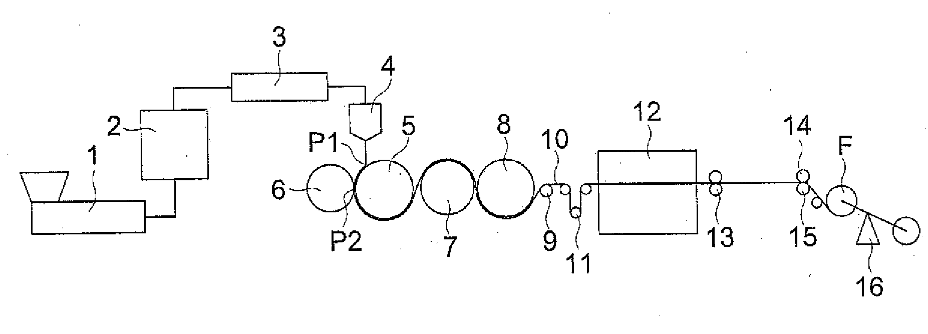
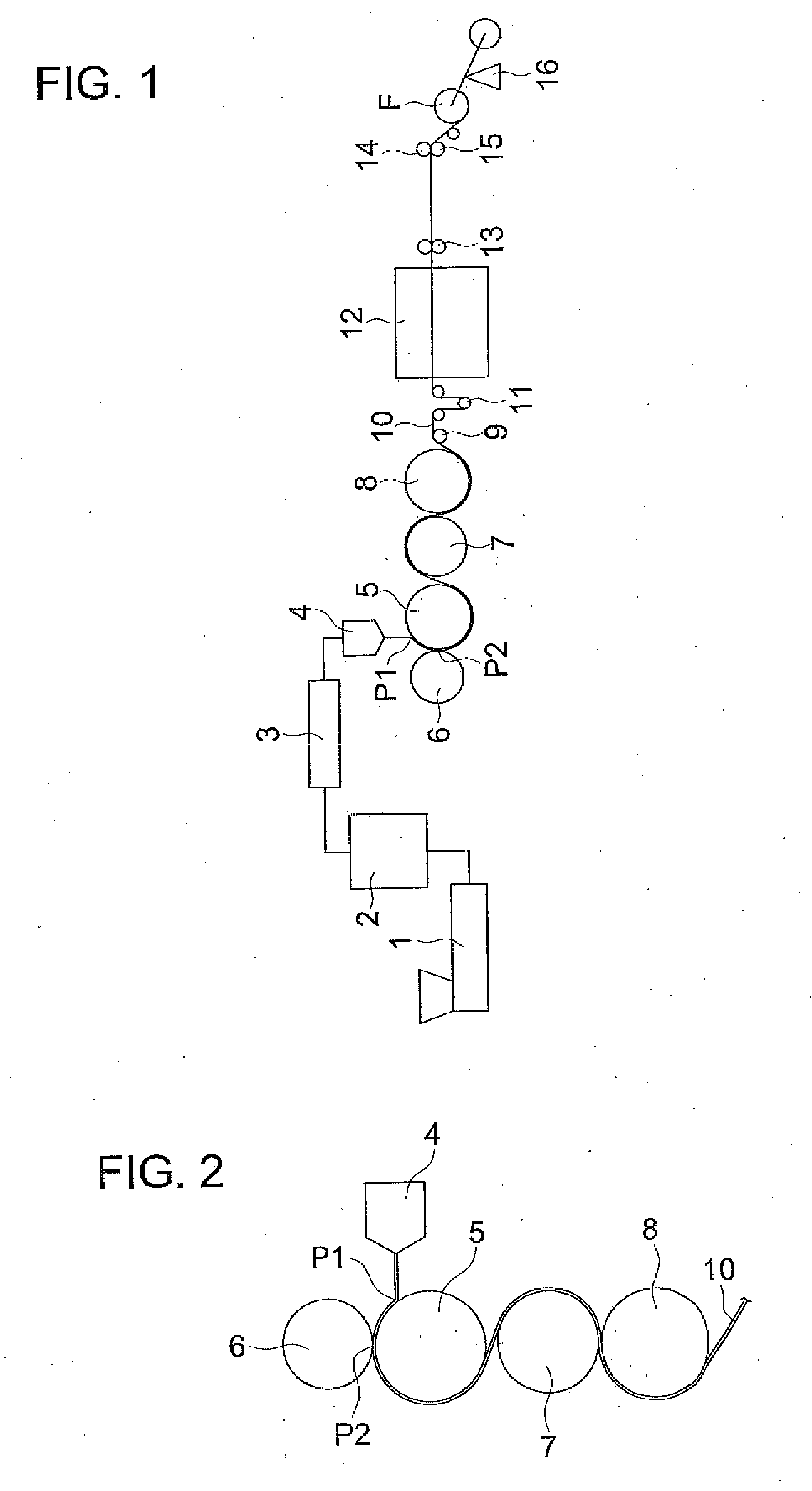
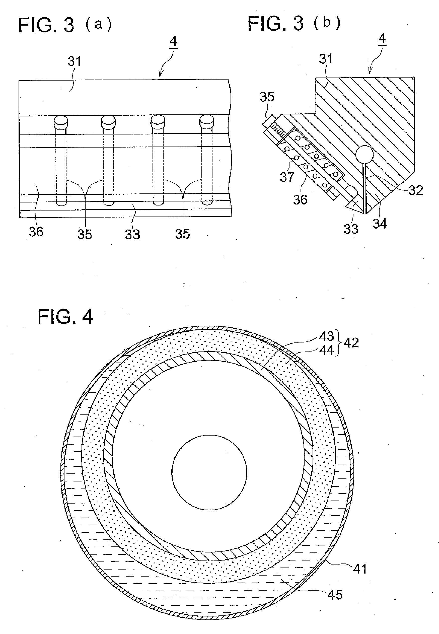
[0319]One hundred parts of the foregoing cellulose ester C-1 were dried under reduced pressure at 70° C. for 3 hours, and cooled to room temperature. The following additives were added into this cellulose ester, and the resulting was melted and mixed at 230° C. to form pellets employing a biaxial extruder. These pellets were melted under nitrogen atmosphere at a melting temperature of 250° C., and extruded from a T type die. After a film was prepared by a film forming method employing an elastic touch roll shown in the forgoing FIG. 4, a knurling treatment of a width of 10 mm and a height of 5 μm at the film ends was carried out, and the film was wound on a winding core at a winding tension of 220 N / m and a taper of 40% to prepare cellulose ester film 1-1 having a winding length of 3200 m, a film width of 1.8 m and a film thickness of 80 μm.

(Additives)Exemplified compound 1-12partsExemplified compoun...

example 2

[0340]Cellulose ester films 2-1-2-6 were prepared similarly to preparation of cellulose ester film 1-1, except that as to additives having been used for preparation of cellulose ester film 1-1 in Example 1, a compound represented by Formula (2), additive 2 and plasticizer 1 were replaced by compounds described in Table 4.

[0341]Further, wrinkles when starting winding, horseback failure and winding core transfer were evaluated by the same method as in Example 1, and after preparing a polarizing plate, front contrast was evaluated as the characteristic evaluation of a liquid crystal display device.

[0342]Evaluated results are shown in Table 4.

TABLE 4CompoundWrinklesCelluloseUVrepresentedwhenHorse-WindingesterCelluloseabsorbentby FormulastartingbackcoreFrontfilm No.esterkind(2)AdditivesPlasticizerwindingfailuretransfercontrastRemarks2-1C-11-1103Additive 2Plasticizer 2AAA815Inv.2-2C-11-1103Additive 3Plasticizer 2AAA805Inv.2-3C-11-1103Additive 3Plasticizer 1AAA805Inv.2-4C-11-1135Additive 3...

example 3

[0344]Cellulose ester films 3-1 and 3-2 were prepared similarly to preparation of cellulose ester film 1-1, except that as to additives having been used for preparation of cellulose ester film 1-1 in Example 1, exemplified compound 103 was replaced by additive 4: Sumilizer GM (produced by Sumitomo Chemical Co., Ltd.) or additive 5: Sumilizer GS (produced by Sumitomo Chemical Co., Ltd.) having an equimolar amount to exemplified compound 103.

[0345]Further, wrinkles when starting winding, horseback failure and winding core transfer were evaluated by the same method as in Example 1, and after preparing a polarizing-plate, front contrast was evaluated as the characteristic evaluation of a liquid crystal display device.

[0346]Cellulose ester films of the present invention 3-1 and 3-2 each containing a UV absorbent of the present invention exhibit excellent properties such as wrinkles when starting winding, horseback failure and winding core transfer. Further, when a polarizing plate prepar...


PUM

PropertyMeasurementUnit
wavelengthaaaaaaaaaa
opticalaaaaaaaaaa

Abstract

In the present invention, provided is an optical film exhibiting less generation of horseback failure, winding core transfer and wrinkles on a film when starting winding, and also provided is a manufacturing method thereof, further together with a polarizing plate and a liquid crystal display device exhibiting high contrast. Also disclosed is an optical film possessing a cellulose ester and a UV absorbent represented by the following Formula (1):
wherein R1 represents
R2 represents a methyl group, a t-butyl group, a t-amyl group or a t-octyl group; R3 represents a substituent; each of R4 and R5 represents a hydrogen atom or a substituent; m is an integer of 0-3; and n is an integer of 0-4.

Description

TECHNICAL FIELD[0001]The present invention relates to an optical film, a method of manufacturing the same, a polarizing plates and a liquid crystal display device.BACKGROUND[0002]Recently, studies and development have been made regarding decrease in product thickness and weight of a note board type personal computer, enlargement of a display and high precision of image in parallel with this development, decrease in thickness, increase in width and improvement of quality of an optical film have also been strongly demanded. Generally, a film made of a cellulose ester is widely utilized as a polarizing plate protective film which is an optical film used for a liquid crystal display device.[0003]Deterioration via UV radiation was inhibited by mixing a UV absorbent such as a benzotriazole based compound, benzophenone based compound or a cyanoacrylate based compound and a salicylic acid based compound. However, since these UV absorbents exhibit low solubility, they easily bleed out, are e...

Claims


Application Information

Patent Timeline
Patent Type & Authority Applications(United States)
IPC IPC(8): C09K19/52C08L1/10B29D11/00
CPCC08K5/1535C08K5/3475C08L1/10C08L1/14G02B1/105Y10T428/1041G02B5/3033G02B5/208C08L1/08G02B1/14C09K2323/031G02B5/30G02F1/1335
Inventor KAWABE, SATOMISAITO, KOICHIYAMADA, RUMIKO
Owner KONICA MINOLTA OPTO
Why Eureka
Try Eureka