Hybrid heating and cooling system

a technology of heating and cooling system and hybrid technology, which is applied in the direction of domestic cooling apparatus, heat pumps, lighting and heating apparatus, etc., can solve the problems of significantly reducing the efficiency of the heating system, significantly impairing the operation of the heat pump, and evaporating freeze, so as to achieve high adaptability, improve efficiency, and facilitate implementation

Inactive Publication Date: 2006-12-28
GEOFURNACE DEV
View PDF11 Cites 61 Cited by
  • Summary
  • Abstract
  • Description
  • Claims
  • Application Information

AI Technical Summary

Benefits of technology

[0012] The present invention provides a hybrid geothermal / air coil heating and cooling system that provides a high level of adaptability and improved efficiency over convention systems. The control system permits selective operation of any two heat exchangers in combination, thereby providing a highly adaptable system that can be controlled to take advantage of the most efficient heating or cooling combinations for varying circumstances. In select modes of operation, the geothermal heat exchanger can be used alternatively to provide energy for indoor heating and outside air coil defrosting. Additionally, the unique circuit of the present invention provides automatic pump down of the isolated heat exchange device during each mode of operation to address potential issues associated with refrigerant imbalance. Further, when geothermal operation is not most efficient, the system is capable of operating in an air-to-air mode utilizing the outdoor air coil. The circuit of the present invention is easily implemented with a small number of relatively inexpensive components. Accordingly, the equipment and installation costs of the system are relatively low.

Problems solved by technology

Experience has revealed that when an air-to-air heat pump is operated in the heating mode at close to freezing temperatures, frost can form on the evaporator.
This can significantly impair operation of the heat pump.
This approach suffers in that it significantly reduces the efficiency of the heating system because heat is removed from the inside of building to defrost the evaporator.
Drawing heat from inside the building can also generate an undesirable cold draft through the duct work.
This type of system is also inefficient because it requires operation of a separate electric heater.

Method used


Image

  • Hybrid heating and cooling system
  • Hybrid heating and cooling system
  • Hybrid heating and cooling system

Examples


Embodiment Construction

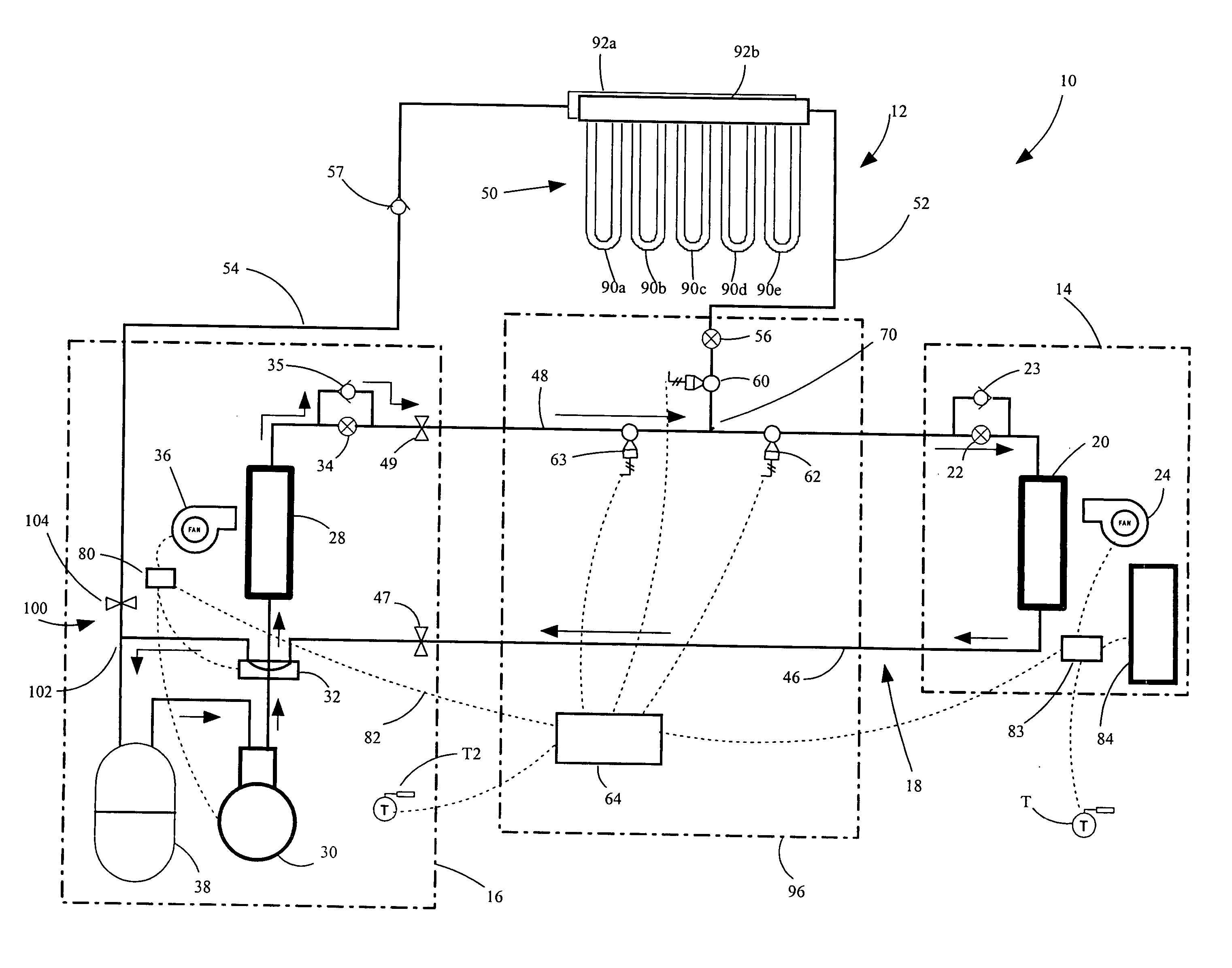
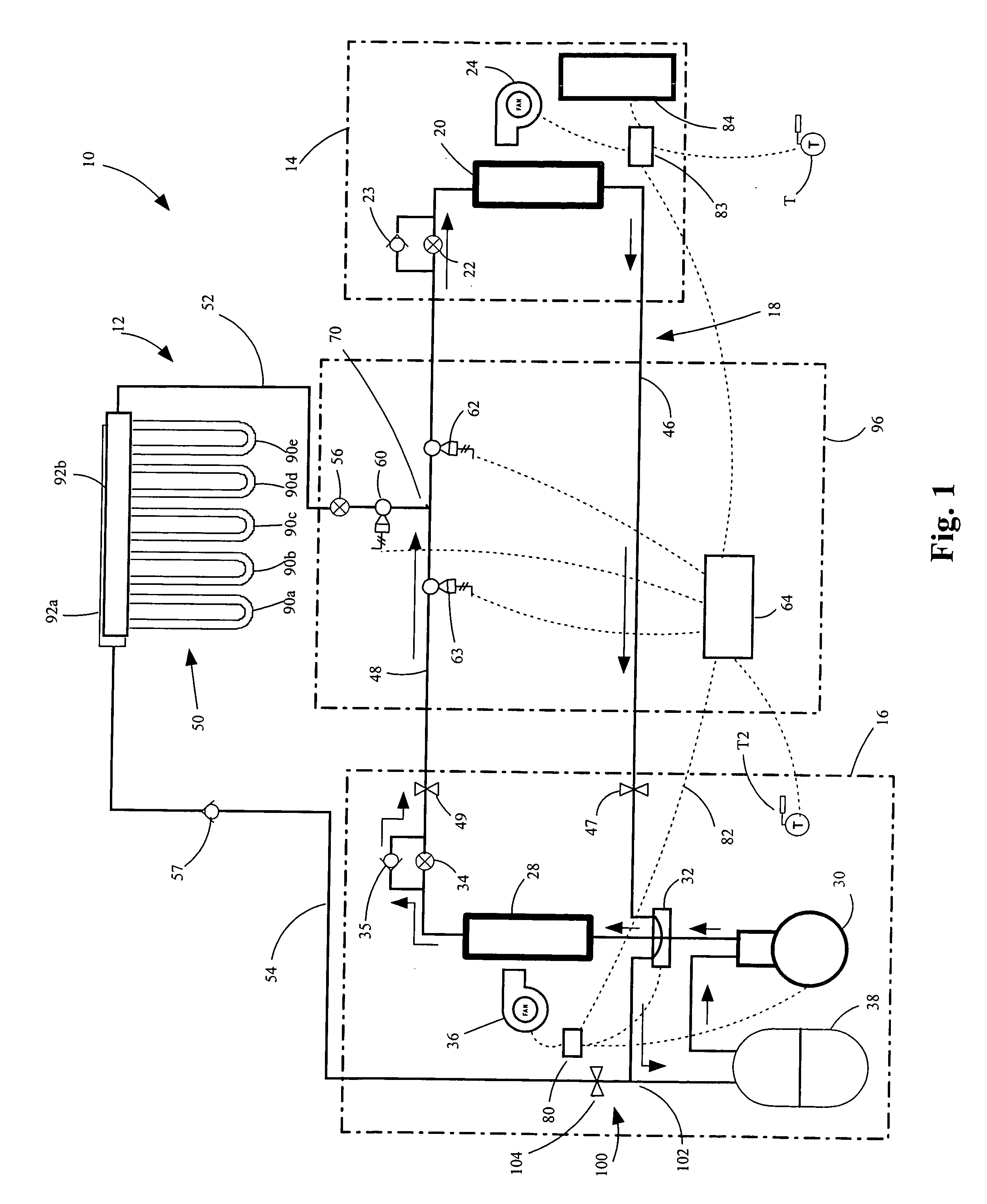
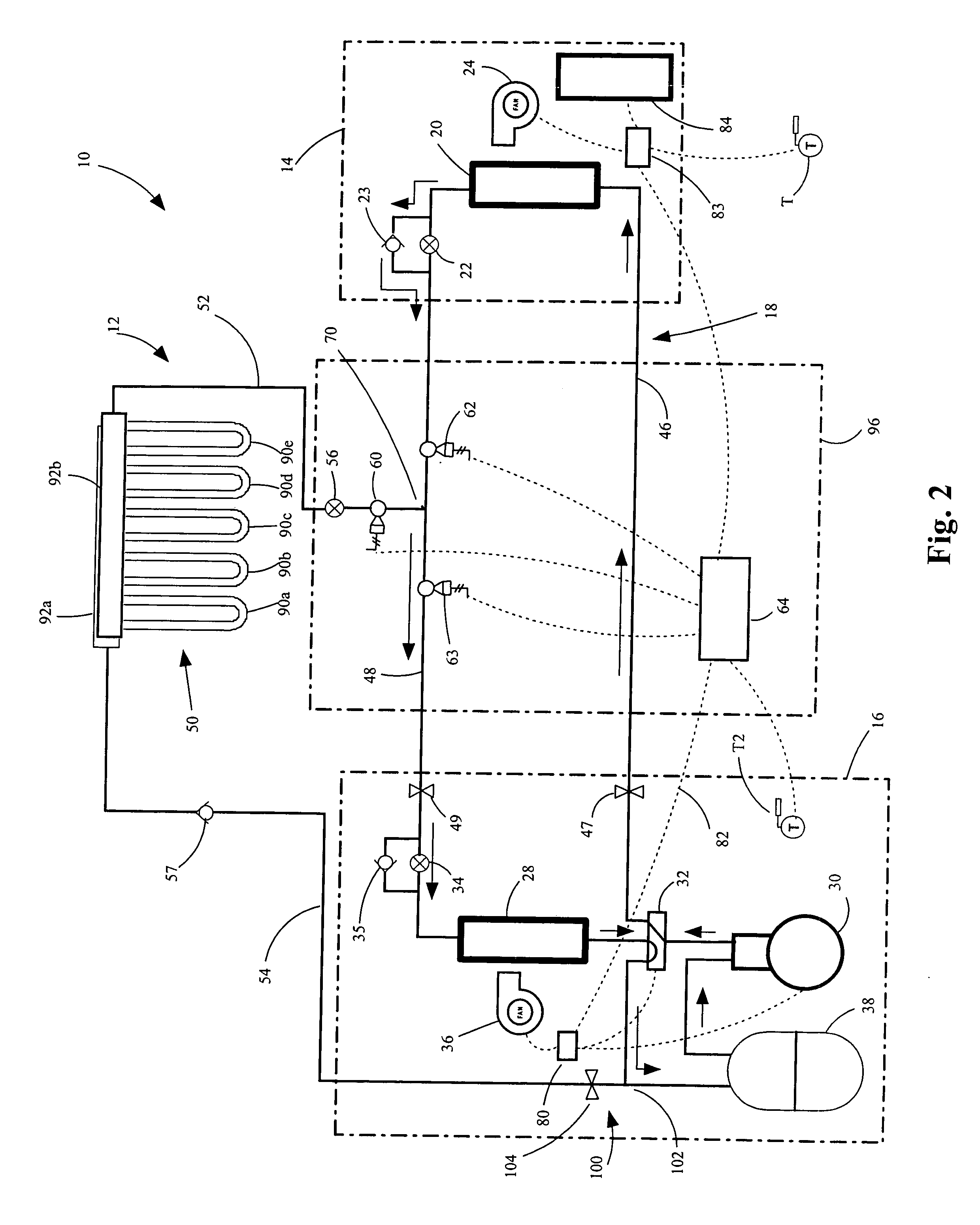
[0019] A heat and cooling system in accordance with an embodiment of the present invention is illustrated in FIG. 1 and generally designated 10. The system 10 generally includes an indoor air coil subcircuit 14, an outdoor air coil subcircuit 16 and a geothermal heat exchanger subcircuit 12. The system 10 includes a control system that permits any two of the three subcircuits to be selectively interconnected to provide heating or cooling as desired. The system 10 operates to either cool or heat a space by transferring heat between the indoor air, the outdoor air or a geothermal heat source. More specifically, in the cooling mode, the system 10 abstracts heat from the indoor air and releases it into the outdoor air, and in the heating modes, the system 10 abstracts heat from the outdoor air or the geothermal heat source and releases it into the indoor air. The system 10 is also capable of defrosting the outdoor air coil by transferring heat from the indoor air or the geothermal heat ...


PUM


Abstract

A heat and cooling system having an indoor air coil subcircuit, an outdoor air coil subcircuit, a geothermal subcircuit, and a control system for selectively operating the system in air-to-air heating, air-to-air cooling, geothermal heating, air-to-air defrost (optionally) and geothermal defrost modes. The various subcircuits may be connected to one another in parallel. The heating and cooling system may include a control system that permits refrigerant to be selectively routed through any two of the heat exchangers to provide the various modes of operation. In one embodiment, the control system may generally include a circuit having a single reversing valve, a plurality of check valves, a plurality of solenoid valves and a plurality of expansion devices.

Description

BACKGROUND OF THE INVENTION [0001] The present invention relates to heating and cooling apparatus, and more particularly to a heating and cooling system having geothermal and air-to-air subcircuits. [0002] Air-to-air heat pumps have been in widespread use throughout the United States for many years. These units operate to exchange heat between outdoor air and inside air. For example, a conventional heat pump can operate in either a heating mode during which heat is drawn from the outdoor air and used in heating the inside of the building or in a cooling mode during which heat is drawn from inside the building and released into the outdoor air. Because these systems transfer rather than generate heat, they are generally more efficient than conventional heating and cooling systems. [0003] Air-to-air heat pumps are available in a variety of designs. A typical air-to-air heat pump includes an outdoor air coil unit located outside of the building, an indoor air coil unit located within t...

Claims


Application Information

Patent Timeline
Patent Type & Authority Applications(United States)
IPC IPC(8): F25D23/12F25B13/00
CPCF25B13/00F25B30/06F25B41/04F25B47/025F25B2400/19F25B2313/009F25B2313/02741F25B2313/0292F25B2313/002F25B41/24
Inventor AMBS, REX K.KIESSEL, THOMAS G.WESTON, DENNIS L.HOLSTINE, JAMES V.
Owner GEOFURNACE DEV
Why Eureka
Try Eureka