Driving device for hybrid vehicle, and hybrid vehicle incorporating the same

a hybrid vehicle and driving device technology, applied in the direction of machines/engines, output power, non-mechanical valves, etc., can solve the problems of sudden torque change, impact before crankshaft stop, and inability to reduce the pressure in the cylinder through the entire compression stroke of the engine, so as to reduce the rotational speed of the engine and reduce the compression pressure inside the engine cylinder.

Active Publication Date: 2006-12-28
YAMAHA MOTOR CO LTD
View PDF12 Cites 34 Cited by
  • Summary
  • Abstract
  • Description
  • Claims
  • Application Information

AI Technical Summary

Benefits of technology

[0023] Another aspect of the present invention involves a method of operating a hybrid vehicle having an internal combustion engine and an electric motor as power sources in which a driving wheel is driven by at least one of the engine and the motor. The vehicle also includes a power distribution device that distributes the power produced by the engine to a first rotary electric machine and to the driving wheel. The method involves reducing a rotational speed of the engine; stopping combustion in the engine; stopping fuel supply to the engine; closing a throttle valve of the engine; and reducing a compression pressure inside an engine cylinder when stopping the engine.

Problems solved by technology

Even with the use of the variable valve mechanism, however, the in-cylinder pressure cannot be reduced through the entire compression stroke of the engine because of limitations on the phase range within which valve timing can be varied.
With this construction, however, in the transition process to stop the rotation of the crankshaft, the compressed in-cylinder pressure restrains the rotation of the crankshaft, which causes a sudden change in torque and hence impact before the crankshaft stops.
That is, in the case where the hybrid drive unit using the power transmission device disclosed in JP 2003-191761 is mounted on a motorcycle, an impact which occurs when the engine is stopped while the vehicle is running or during transition to an operating state without combustion but with continuing rotation of the crankshaft and reciprocation of the piston(s) is an unintentional increase and decrease in propulsion force that need to be decreased.
However, a motorcycle has a limited mounting space compared to an automobile and thus cannot accommodate a battery which becomes larger as its charging capacity increases, or a larger motor for producing increased torque.

Method used


Image

  • Driving device for hybrid vehicle, and hybrid vehicle incorporating the same
  • Driving device for hybrid vehicle, and hybrid vehicle incorporating the same
  • Driving device for hybrid vehicle, and hybrid vehicle incorporating the same

Examples


Embodiment Construction

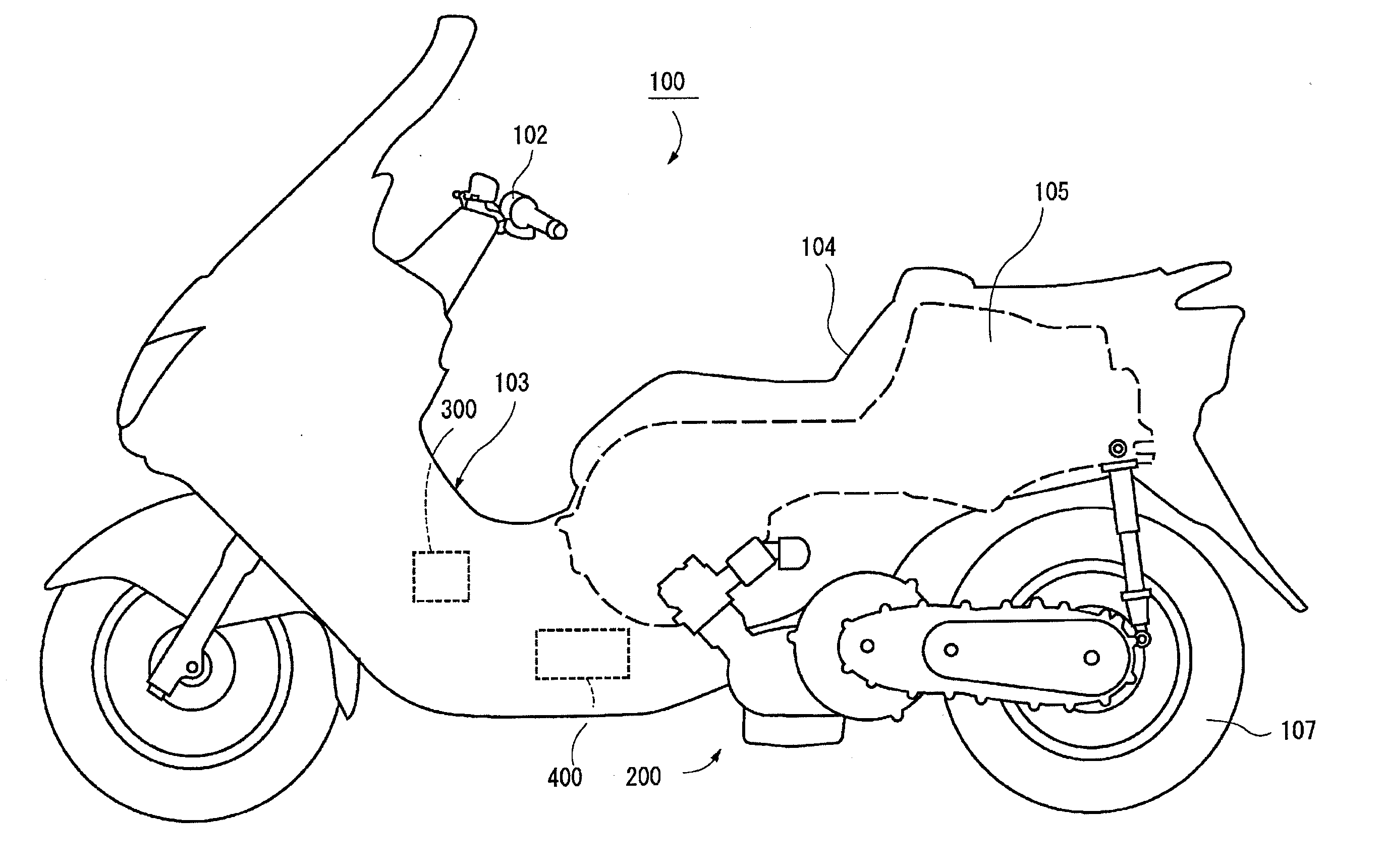
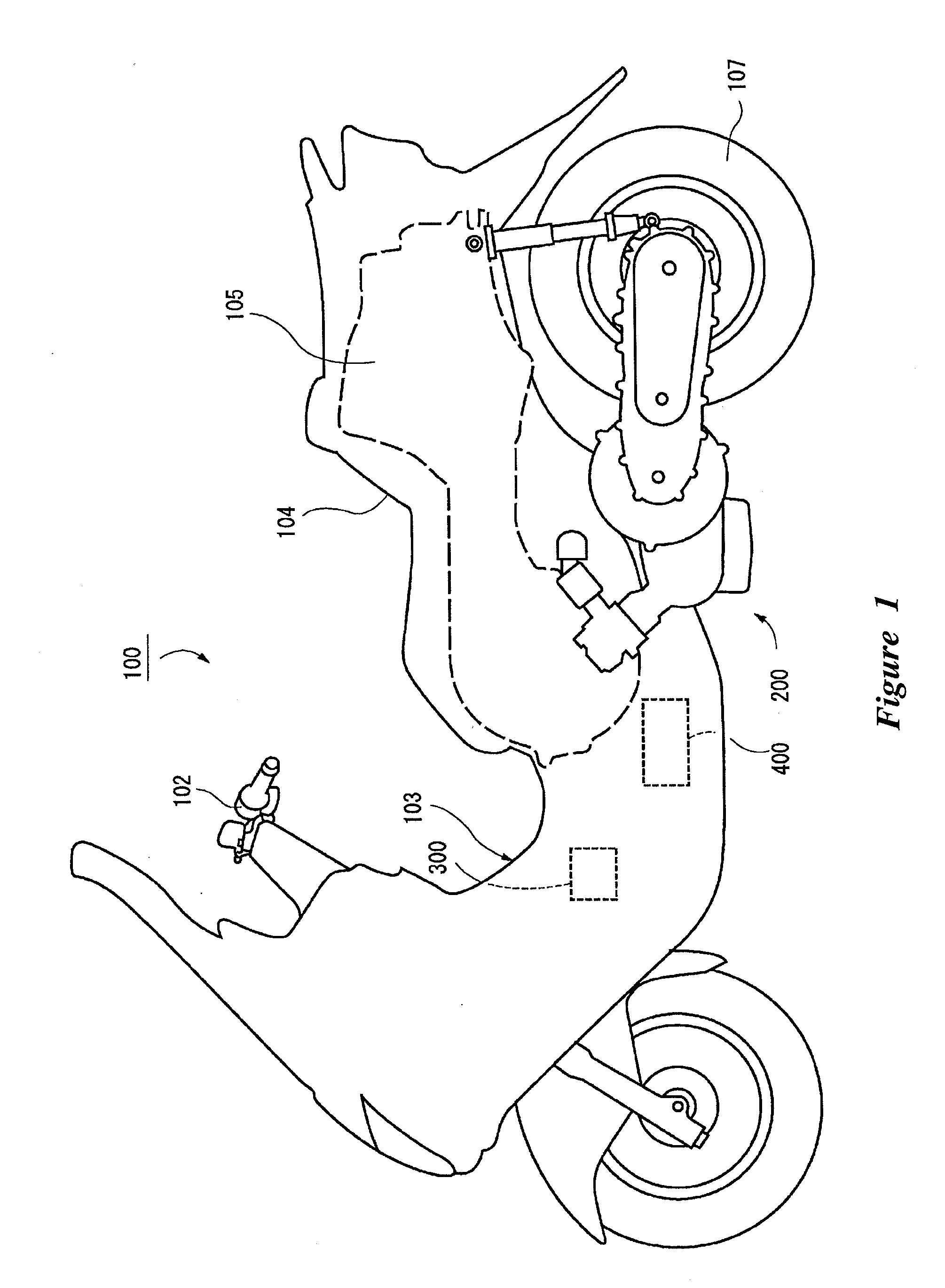
[0034]FIG. 1 is a schematic left side view illustrating the construction of an essential part of a scooter-type motorcycle as an example of a hybrid vehicle incorporating a driving device for a hybrid vehicle according to an embodiment of the present invention. The driving device is described and illustrated in connection with this type of vehicle as has particular applicability to scooter-type vehicle; however, the driving device can be used with other types of vehicles as well.

[0035] The hybrid vehicle shown in FIG. 1 is a series-parallel hybrid scooter-type motorcycle in which a wheel is driven using an internal combustion engine and / or an electric motor as power sources. Specifically, in the hybrid vehicle (hereinafter referred to as “scooter-type motorcycle”), the engine power is split by a power split mechanism into two parts with a variable split ratio, of which one part is used to drive the wheel directly and the other part is used to generate electricity. In this embodimen...


PUM


Abstract

An engine produces power, which is distributed by a power distribution device to an electric generator and a rear wheel. A motor produces power other than that produced by the engine to drive the rear wheel. A battery stores electricity generated by the electric generator and supplies electricity to the electric generator and the motor. A hybrid control unit (HCU) controls the engine, the electric generator and the motor. The HCU drives a decompression device provided in the engine to reduce the pressure inside an engine cylinder created while cranking the engine, in order to stop the engine.

Description

CROSS-REFERENCE TO RELATED APPLICATIONS [0001] The present application is based on and claims priority under 35 U.S.C. 119 to Japanese Patent Application No. 2005-184142, filed on Jun. 23, 2005, the entire contents of which are incorporated by reference and should be considered part of this specification. FIELD OF THE INVENTION [0002] The present invention relates to a driving device for a hybrid vehicle using plural driving sources to operate, and to a hybrid vehicle having said driving device. BACKGROUND OF THE INVENTION [0003] There is interest, from an environmental point of view, to reduce the discharge of environmental pollutants from engine-driven vehicles as much as possible. In consideration of this, hybrid vehicles have been developed which utilize an electric motor in addition to an internal combustion engine to drive a driving wheel or driving wheels of the vehicle using the electric motor. [0004] Hybrid vehicles achieve reductions in noise and air pollution by using mai...

Claims


Application Information

Patent Timeline
Patent Type & Authority Applications(United States)
IPC IPC(8): B60K6/00B60K6/445B60L50/16B60W10/06B60W10/08B62M23/02F02D13/08F02D29/02
CPCB60G2204/30Y02T10/70B60K6/44B60L11/14B60L2200/12B60W10/06B60W10/08B60W2510/244B60W2520/10B60W2540/10B60W2540/12B60W2710/0605B60W2710/0616B60W2710/0661B60Y2200/12B62K2202/00B62K2204/00F01L9/04F01L13/0005F01L13/065F01L13/08F01L2800/01F01L2800/03F02D41/042Y02T10/623Y02T10/6286Y02T10/7077B60L2250/26B60L2250/28Y10S903/902B60K1/02B60L50/16Y02T10/62Y02T10/7072F01L9/20
Inventor KATSUHIRO, ARAISAITOU, TETSUSHI
Owner YAMAHA MOTOR CO LTD
Why Eureka
Try Eureka