Plasma source with discharge inducing bridge and plasma processing system using the same

Active Publication Date: 2006-12-28
NEW POWER PLASMA CO LTD
View PDF7 Cites 28 Cited by
  • Summary
  • Abstract
  • Description
  • Claims
  • Application Information

AI Technical Summary

Benefits of technology

[0016] It is another object to provide a plasma source and plasma processing system able to gen

Problems solved by technology

Any increase in the radio frequency power, however, increases ion impact energy.
Consequently, the radio frequency power must be limited to prevent damage caused by ion impact.
It is not easy however, to uniformly produce large-area high-density plasma by merely increasing the number

Method used


Image

  • Plasma source with discharge inducing bridge and plasma processing system using the same
  • Plasma source with discharge inducing bridge and plasma processing system using the same
  • Plasma source with discharge inducing bridge and plasma processing system using the same

Examples


embodiment i

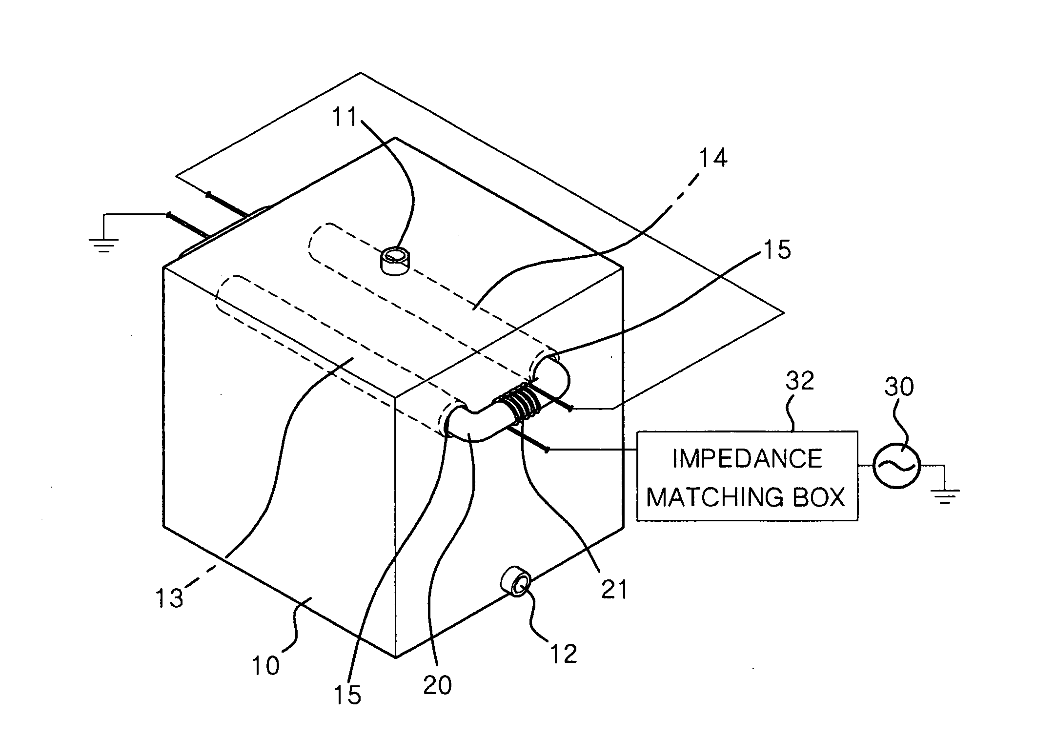
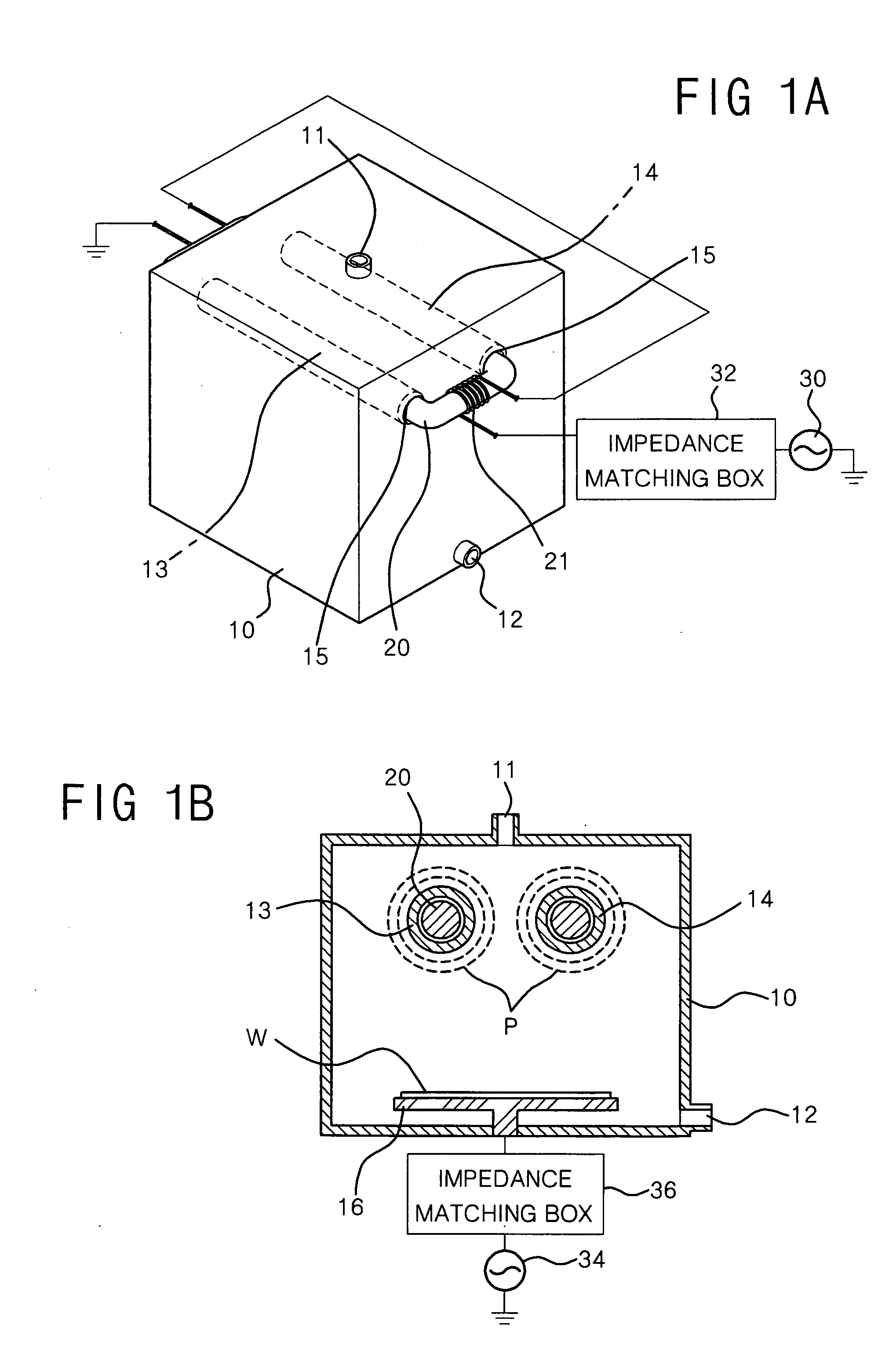
[0112]FIGS. 1A and 1B are a perspective view and a cross-sectional view, respectively, of a plasma processing chamber according to the first embodiment of the present invention.

[0113] Referring to FIGS. 1A and 1B, the plasma processing chamber includes chamber housing 10 and two discharge inducing bridges 13 and 14 positioned inside chamber housing 10. Discharge inducing bridges 13 and 14 are linear hollow tubes. Toroidal magnetic core 20 is mounted in discharge inducing bridges 13 and 14, and magnetic core 20 with winding coil 21 forms a transformer. Winding coil 21 is electrically connected to power supply source 30 supplying radio frequency to the primary winding of the transformer, through impedance matching box 30.

[0114] Chamber housing 10 includes a number of holes 15 formed in two sidewalls opposed to each other. Both ends of each of discharge inducing bridges 13 and 14 are connected to holes 15. A passage within chamber housing 10 from the outside of chamber housing 10 is ...

embodiment ii

[0138]FIGS. 6A and 6B are a projection view and a cross-sectional view, respectively, of a plasma processing chamber according to a second embodiment of the present invention.

[0139] Referring to FIGS. 6A and 6B, the plasma processing chamber according to the second embodiment generates the inductive coupled plasma P in the same manner as the plasma processing chamber according to the first embodiment described above. Thus, a repeated description thereof will not be presented.

[0140] In the plasma processing chamber, two susceptors 540 are positioned at two sidewalls opposed to each other inside chamber housing 510. Two discharge inducing bridges 522 are horizontally positioned in a vertical plane and equally spaced apart from two susceptors 540. Magnetic core 520 with winding coil 520 is mounted in the discharge inducing bridges 522.

[0141] Gas entrance 511 is formed in the ceiling of chamber housing 510. The gas entrance 510 is preferably positioned above discharge inducing bridge...

embodiment iii

[0146]FIGS. 8A, 8B and 8C are a projection view, an exploded view and a cross-sectional view, respectively, of plasma processing chamber 1000 according to a third embodiment of the present invention.

[0147] Referring to FIGS. 8A, 8B and 8C, plasma processing chamber 1000 includes chamber housing 1110 having susceptor 1101 on which work substrate W is placed; and gas supply unit 1200 positioned on chamber housing 1110.

[0148] A plural number of discharge inducing bridges 1300 are horizontally positioned in a horizontal manner at an upper part of chamber housing 1110, from first sidewall 1111 of 8 chamber housing 1110 to second sidewall 1112 opposed to first sidewall 1111, above susceptor 1101. Gas exit 1105 is positioned at a lower part of chamber housing 1110 and is connected to vacuum pump 1104.

[0149] Holes 1113 are formed in two sidewalls 1111 and 1112 of chamber housing 1110, from and to which discharge inducing bridges 1300 are connected. Holes 1113 receive both ends of each di...


PUM

PropertyMeasurementUnit
Pressureaaaaaaaaaa
Poweraaaaaaaaaa
Flow rateaaaaaaaaaa

Abstract

A plasma source with discharge inducing bridges and a plasma processing system using the same. The plasma source may be constructed with a number of discharge inducing bridges, each discharge inducing bridge containing a magnetic core with a primary winding of a transformer. The discharge inducing bridges are positioned so as to face a susceptor. Each discharge inducing bridge is a hollow tube. When the electrical current of the primary winding of the transformer is driven, magnetic flux is induced to the magnetic core, so that inductive coupled plasma is formed around the discharge inducing bridges, and a plasma discharge is evenly induced horizontally/vertically along the discharge inducing bridges, so that uniform large-area high-density plasma is generated.

Description

CLAIM OF PRIORITY [0001] This application makes reference to, incorporates the same herein, and claims all benefits accruing under 35 U.S.C. §119 from five applications earlier filed in the Korean Intellectual Property Office on the 23rd of May 2005 and there duly assigned Ser. No. 10-2005-0043232, filed on the 15th of Jun. 2005 and assigned Ser. No. 10-2005-0051638, filed on the 16th of Feb. 2006 and assigned Ser. No. 10-2006-0015143, and filed on the 10th of May 2006 and assigned Ser. Nos. 10-2006-0042062 and 10-2006-42073, copies of which are annexed to this application. BACKGROUND OF THE INVENTION [0002] 1. Field of the Invention [0003] The present invention relates generally to a radio frequency plasma source and, more particularly, to a plasma processing system using a radio frequency plasma source. [0004] 2. Discussion of the Related Art [0005] Plasma is a highly ionized gas which contains equal numbers of positive ions and electrons. Plasma discharge is used for gas excitati...

Claims


Application Information

Patent Timeline
IPC IPC(8): B23K9/00B23K9/02
CPCH01J37/321H01J37/32009
Inventor CHOI, DAE-KYUWI, SOON-IM
Owner NEW POWER PLASMA CO LTD
Why Eureka
Try Eureka