Apparatus and method for laminating tape on electrode of rechargeable battery

a rechargeable battery and electrode technology, applied in the direction of wound/folded electrode electrodes, cell components, manufacturing tools, etc., can solve the problems of deterioration of stability and reliability of rechargeable batteries, electric short circuits, and increase of the tension of the electrode assembly, so as to control the tension of the electrode

Active Publication Date: 2006-12-28
SAMSUNG SDI CO LTD
View PDF5 Cites 14 Cited by
  • Summary
  • Abstract
  • Description
  • Claims
  • Application Information

AI Technical Summary

Benefits of technology

[0009] In another embodiment, the first buffering section includes an electric motor; a rotatable conveying roller connected by a belt to the motor for conveying the electrode from the supplying section; and a friction roller which comes into close contact with the conveying roller in order for the electrode to be interposed between the conveying roller and the friction roller, the friction roller rotating along with the conveying roller so as to control a tension of the electrode. This embodiment may further include a supporting roller for supporting the electrode; and an elevating roller for delaying a movement of the electrode, wherein the supporting roller is mounted at a rear portion of the conveying roller, and the elevating roller is mounted between the conveying roller and the supporting roller so as to descend due to its weight during the laminating of the tape in the laminating section and to ascend due to tension of the electrode during the feeding of the electrode in the feeding section.
[0010] The laminating section may include a lower tape laminating section for laminating the tape to the end portions of the active materials on a lower surface of the electrode; and an upper tape laminating section for laminating the tape to the end portions of the active materials on an upper surface of the electrode. The lower tape laminating section may further include a supporter disposed at an upper portion of the lower tape laminating section, for supporting the electrode; a pressing element disposed at a lower portion of the lower tape laminating section, for laminating the tape; and a vision portion mounted at a side of the pressing portion, for detecting a position of the end portions of the active materials on a lower surface of the electrode. In another embodiment, the lower tape laminating section includes an electric motor mounted at a lower portion of the lower tape laminating section; a ball screw connected to the electric motor; and a pressing element coupled to the ball screw, so as to control a position of the pressing element.
[0011] The upper tape laminating section may include a supporter disposed at a lower portion of the upper tape laminating section, for supporting the electrode; a pressing element disposed at an upper portion of the upper tape laminating section, for laminating the tape; and a vision portion mounted at a side of the pressing element, for detecting a position of the end portions of the active materials. The upper tape laminating section may further include an electric motor mounted at a lower portion of the upper tape laminating section and a ball screw connected to the electric motor and coupled to the supporter, so as to control a position of the supporter.

Problems solved by technology

However, various problems may occur when the tension of the electrode assembly increases.
One of the problems is that the end portion of the active material layer having one polarity, i.e. a sharp end portion of the active material forming a boundary between the non-coated portion of the current collector and the active material, can extend through a separator so as to cause an electric short circuit in an active material layer or on an electrode having the other polarity.
The electric short circuiting of the active material or the electrode causes the deterioration of the stability and the reliability of the rechargeable battery.
It is known that the above-mentioned problem frequently occurs in the electrode assembly wound in a cylindrical shape.
Thus, the rigidity of the separator may decrease to allow the end portion of the active material layer to easily cut the separator, thereby causing the electric short circuiting more easily.

Method used


Image

  • Apparatus and method for laminating tape on electrode of rechargeable battery
  • Apparatus and method for laminating tape on electrode of rechargeable battery
  • Apparatus and method for laminating tape on electrode of rechargeable battery

Examples


Embodiment Construction

[0026] Hereinafter, various embodiments of the present invention will be described with reference to the accompanying drawings so that a person skilled in the art can perform the present invention.

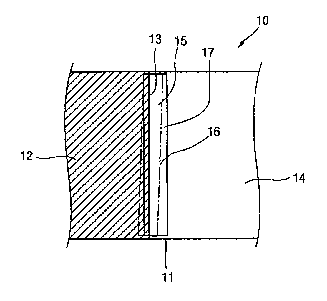
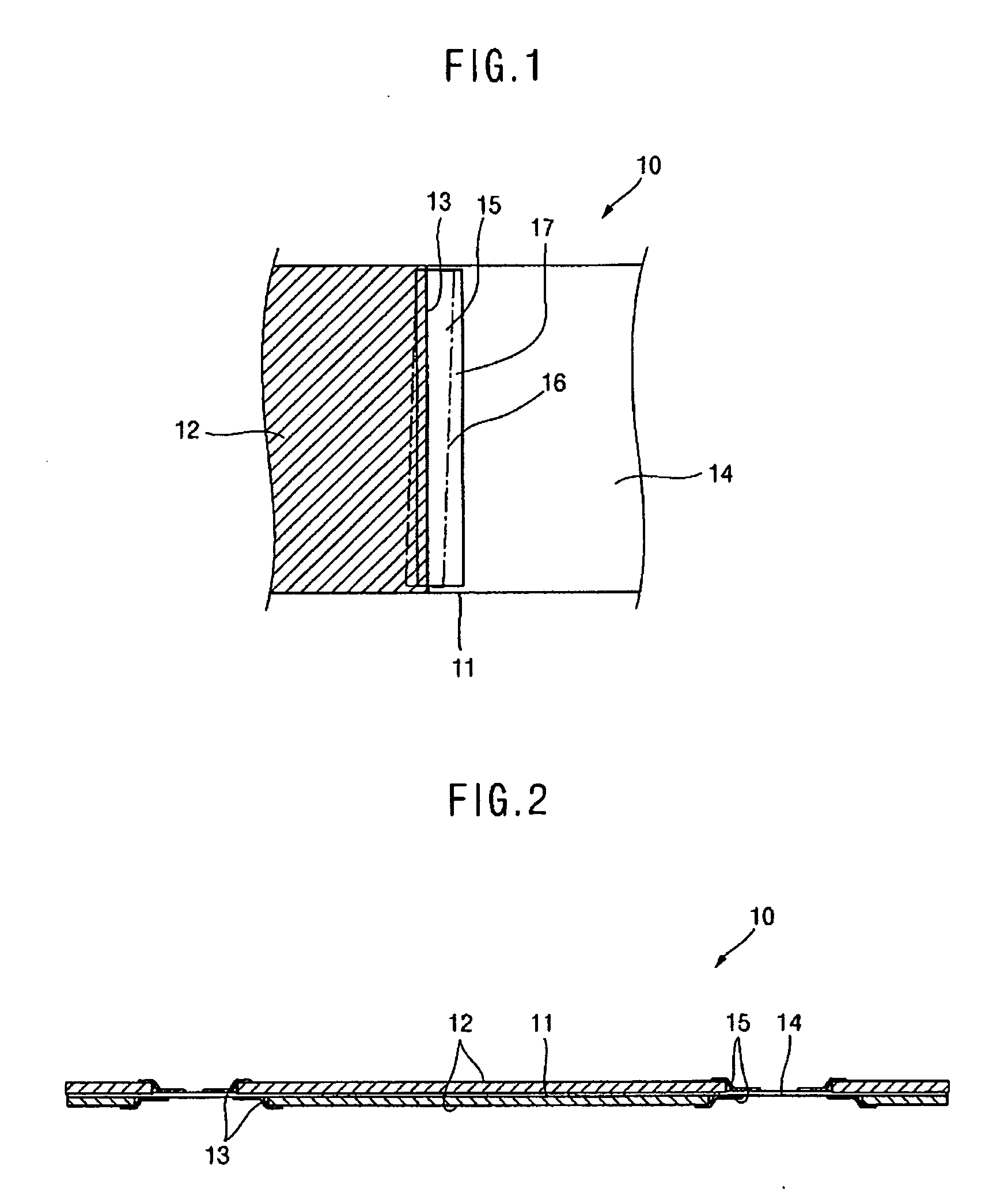
[0027] As shown in FIG. 1, the electrode 10 is formed with a foil shaped current collector 11 for collecting current, and an active material 12 coated at a desired thickness and area on a surface of the current collector 11. An end portion 13 of the active material 12 exists at the boundary between the active material 12 and a non-coated portion 14 on which the active material 12 is not coated. Furthermore, on the electrode 10, a tape 15 having a desired width and length is laminated on an end portion 13 of the active material 12, according to this embodiment of the present invention. The electrode 10 is approved when the tape 15 has been laminated on the end portion 13 of the active material 12 so as to be substantially parallel with the end portion 13, and is disapproved when the tape 1...


PUM

PropertyMeasurementUnit
distancesaaaaaaaaaa
timeaaaaaaaaaa
tensionaaaaaaaaaa

Abstract

An apparatus for laminating tape on an electrode for a rechargeable battery includes a supplying section for supplying an electrode having a current collector with surfaces on which active materials are coated at constant distances from each other. The electrode is wound a plurality of times on the supplying section. The apparatus also includes a first buffering section for carrying the electrode from the supplying section at a constant rate and a laminating section for receiving the electrode from the first buffering section and stopping movement of the electrode for a predetermined time. The laminating section laminates tape on end portions of the active materials after stopping the movement. A feeding section conveys the electrode from the laminating section at a desired pitch. A second buffering section carries the electrode from the feeding section at a predetermined rate and a winding section receives the electrode from the second buffering section.

Description

CROSS-REFERENCE TO RELATED APPLICATION [0001] This application claims priority to and the benefit of Korean Patent Application No. 10-2005-0034727, filed Apr. 26, 2005, the entire content of which is incorporated herein by reference. BACKGROUND OF THE INVENTION [0002] Generally, in rechargeable batteries such as lithium ion battery and lithium polymer battery, an electrolyte and an electrode assembly are contained together in a can. The electrode assembly includes an anode electrode, a separator, and a cathode electrode. The anode electrode is formed with a foil shaped anode current collector and an anode active material coated on a surface thereof, while the cathode electrode also is formed with a foil shaped cathode current collector and a cathode active material coated on a surface thereof. The current collectors of the electrodes have non-coated portions on which the active material is not coated and to which a conductive tap is usually welded in order to connect the electrode t...

Claims


Application Information

Patent Timeline
Patent Type & Authority Applications(United States)
IPC IPC(8): B21B27/06H05B3/02H01M4/04
CPCH01M2/168H01M2/26Y10T156/1734H01M10/0431H01M10/0409Y02E60/10H01M50/461D05B85/02
Inventor OH, DONG ICKYOO, TAEJUN
Owner SAMSUNG SDI CO LTD
Why Eureka
Try Eureka