[0002] The invention generally relates to a temperature sensor based
on resistance measurement that may be used in a radiant heater in an electric cooking appliance, as well as a radiant heater using a conventional filament,
halogen lamp or a halogen radiant heater as a temperature sensor.
[0003] It is known to provide the cooking areas of heating elements with a
sensor system that switches the heating means off when the heating elements reach a maximum permitted temperature. Generally, use is made of a rod-type
thermostat made from two different materials with different
thermal expansion coefficients. As a result of heating the different materials to a predetermined temperature, two contacts are separated from each other so that the power supply to the heating device of the cooking area is interrupted. Such a rod-type thermostat is disadvantageous in that a change to the switching point requires considerable effort and that the rod-type thermostats only react slowly to temperature changes.
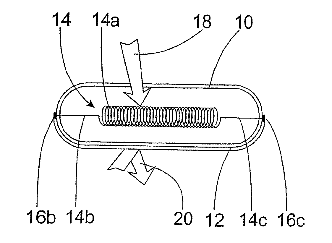
[0015] The sensor element may be encapsulated in a envelope that advantageously has at least, in part, a transparent portion for heat
radiation, and it mechanically protects the temperature sensor. It can also constitute an electrical insulating layer so that it is possible to fit the temperature sensor adjacent to conductive surfaces. As a result of the high transparency for
thermal radiation, it is ensured that the sensor element is reached by the
thermal radiation and consequently a resistance change occurs as heat is detected.
[0003] It is known to provide the cooking areas of heating elements with a
sensor system that switches the heating means off when the heating elements reach a maximum permitted temperature. Generally, use is made of a rod-type thermostat made from two different materials with different
thermal expansion coefficients. As a result of heating the different materials to a predetermined temperature, two contacts are separated from each other so that the power supply to the heating device of the cooking area is interrupted. Such a rod-type thermostat is disadvantageous in that a change to the switching point requires considerable effort and that the rod-type thermostats only react slowly to temperature changes.
[0019] According to another embodiment of the invention, the envelope is wholly or partly constructed with at least one layer of a mechanically stable material, preferably
metal. Such a stabilizing layer leads to
reduced susceptibility to mechanical damage and provide an increase in the durability of the temperature sensor.
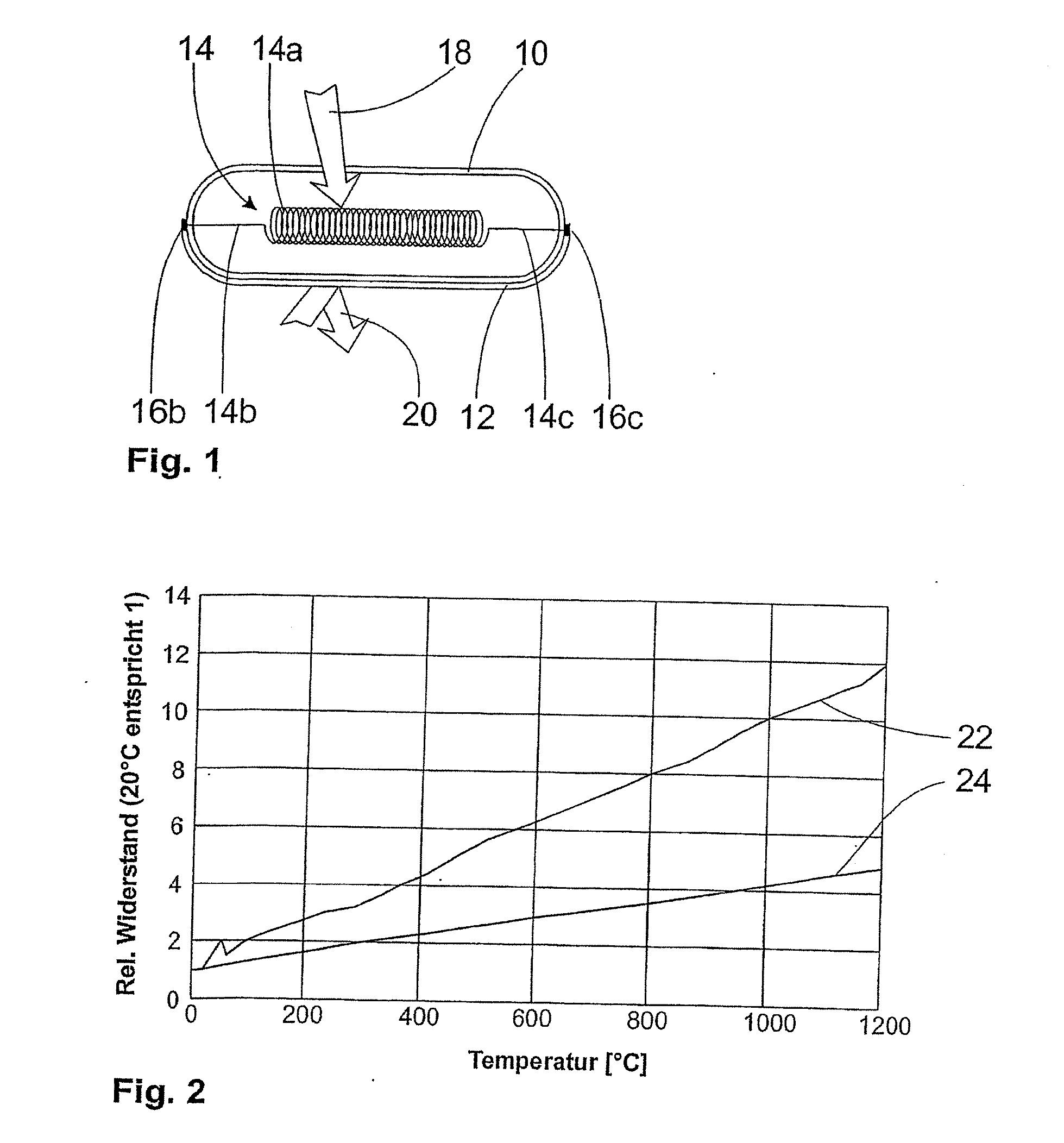
[0025] According to another embodiment of the invention, the sensor element material is a
cobalt-iron
alloy, e.g., an
alloy with approximately 70%
cobalt-iron. Such a material is obtainable under the designation “CF 25” from the firm Vacuumschmelze.
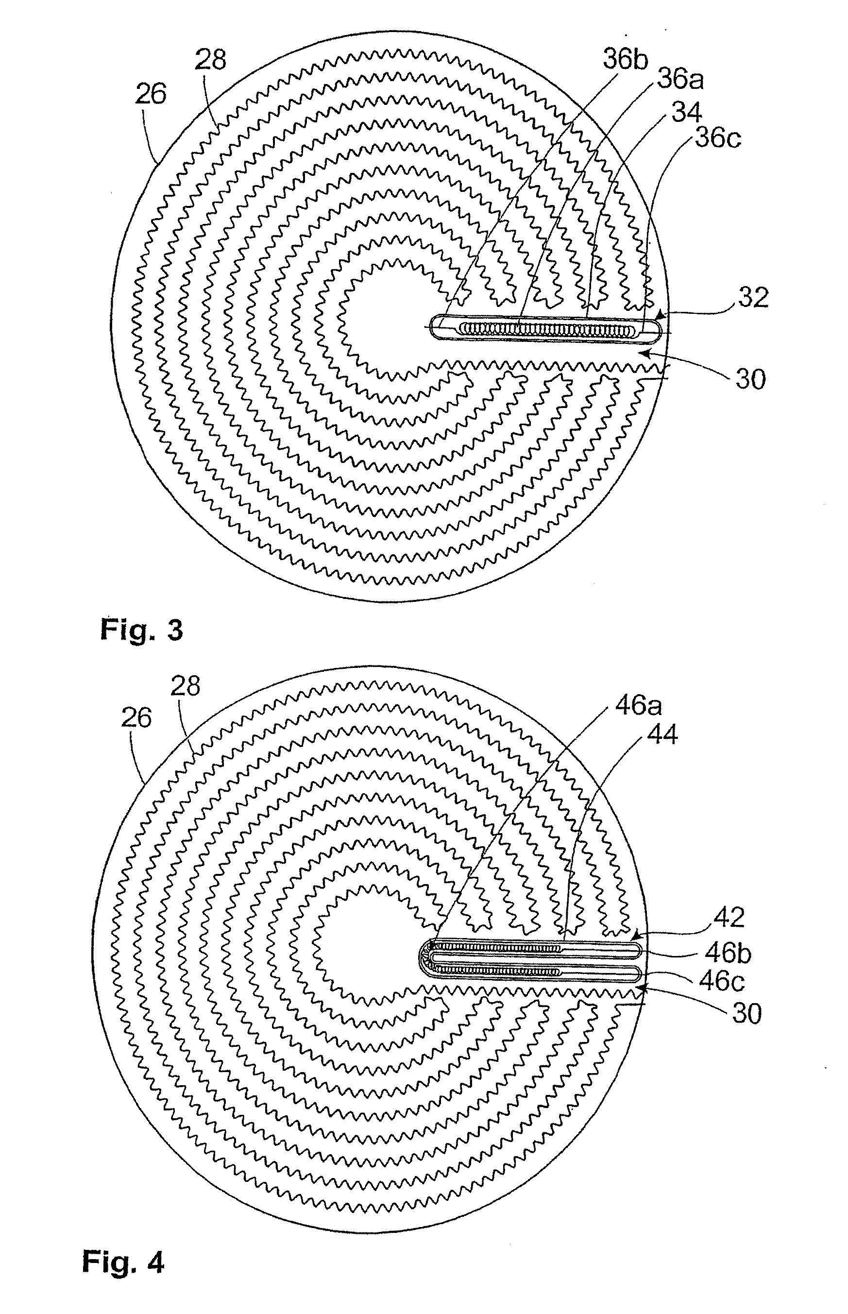
[0018] According to another embodiment of the invention, the envelope is made from an insulating material, such as preferably glass,
ceramic or
quartz, or has several
layers, of which the innermost layer is an insulating material. The insulating material makes it possible to fit the temperature sensor directly to electrically conducting components, particularly of a
heating element. In the case of envelopes with several
layers, it is possible to make only one layer insulating, while allowing the other
layers fulfil other functions.
[0018] According to another embodiment of the invention, the envelope is made from an insulating material, such as preferably glass,
ceramic or
quartz, or has several layers, of which the innermost layer is an insulating material. The insulating material makes it possible to fit the temperature sensor directly to electrically conducting components, particularly of a
heating element. In the case of envelopes with several layers, it is possible to make only one layer insulating, while allowing the other layers fulfil other functions.
[0013] Many modifications and other embodiments of the inventions set forth herein will come to mind to one skilled in the art to which these inventions pertain having the benefit of the teachings presented in the foregoing descriptions and the associated drawings. Therefore, it is to be understood that the inventions are not to be limited to the specific embodiments disclosed and that modifications and other embodiments are intended to be included within the scope of the appended claims. Although specific terms are employed herein, they are used in a generic and descriptive sense only and not for purposes of limitation.

