

Compact heat exchanging device based on microfabricated heat transfer surfaces
a heat exchanger and micro-fabricated technology, applied in the direction of heat exchanger details, domestic cooling apparatus, semiconductor/solid-state device details, etc., can solve the problems of unsatisfactory performance parameters, inability to meet the needs of heat exchangers, and disadvantageous two-dimensional known heat pipes and capillary pump loops, and achieve low pressure drop and high heat transfer performance.
- Summary
- Abstract
- Description
- Claims
- Application Information
AI Technical Summary
Benefits of technology
Problems solved by technology
Method used
Image

Examples
Embodiment Construction
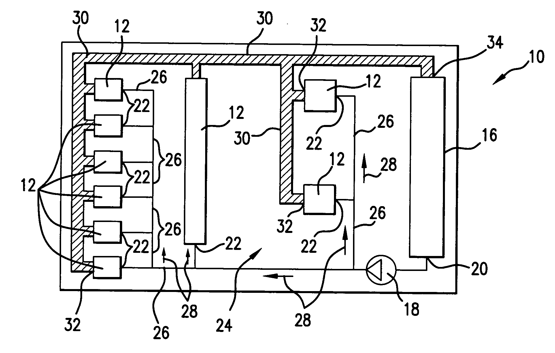
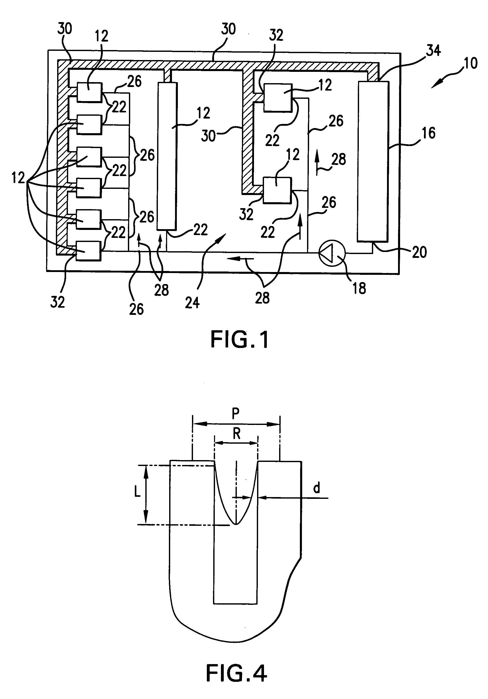
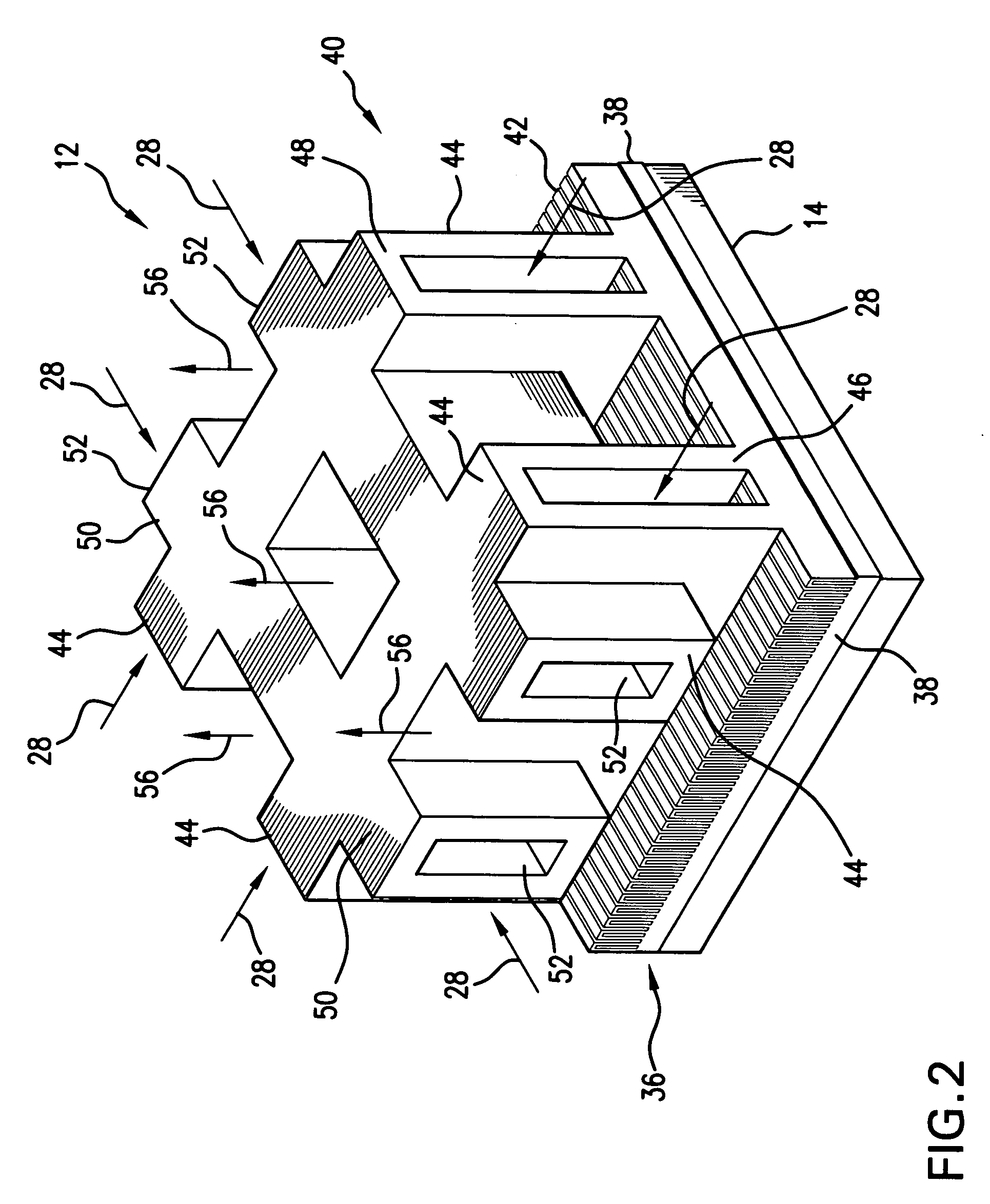
[0048] Referring to FIG. 1, a cooling system 10 includes a plurality of heat exchanging modules 12 attached to a heat generating object 14 (best shown in FIG. 2), a microchannel condenser 16, and a pump 18 connected between an output 20 of the microchannel condenser 16 and inlets 22 of the heat exchanging modules 12. A system 24 includes supply tubing 26 for supplying cold heat exchange medium 28 to the inlets 22 of the heat exchanging modules 12 and tubing 30 for removing the heated fluid medium 28 from outputs 32 of the heat exchanging module 12 to the microchannel condenser 16.
[0049] The cooling system 10 is preferably operable in either one-phase or two-phase mode of operation, as described in further paragraphs. The cooling system 10 is preferably implemented as a self-contained hermetic system which may be contained in a housing (not shown) for being attached as a whole to an object which generates heat, such as, for example, high powered phased arrays, radars, and the like. ...
PUM
 Abstract
Description
Claims
Application Information