Motor control apparatus
- Summary
- Abstract
- Description
- Claims
- Application Information
AI Technical Summary
Benefits of technology
Problems solved by technology
Method used
Image

Examples
first embodiment
[0028] (First embodiment)
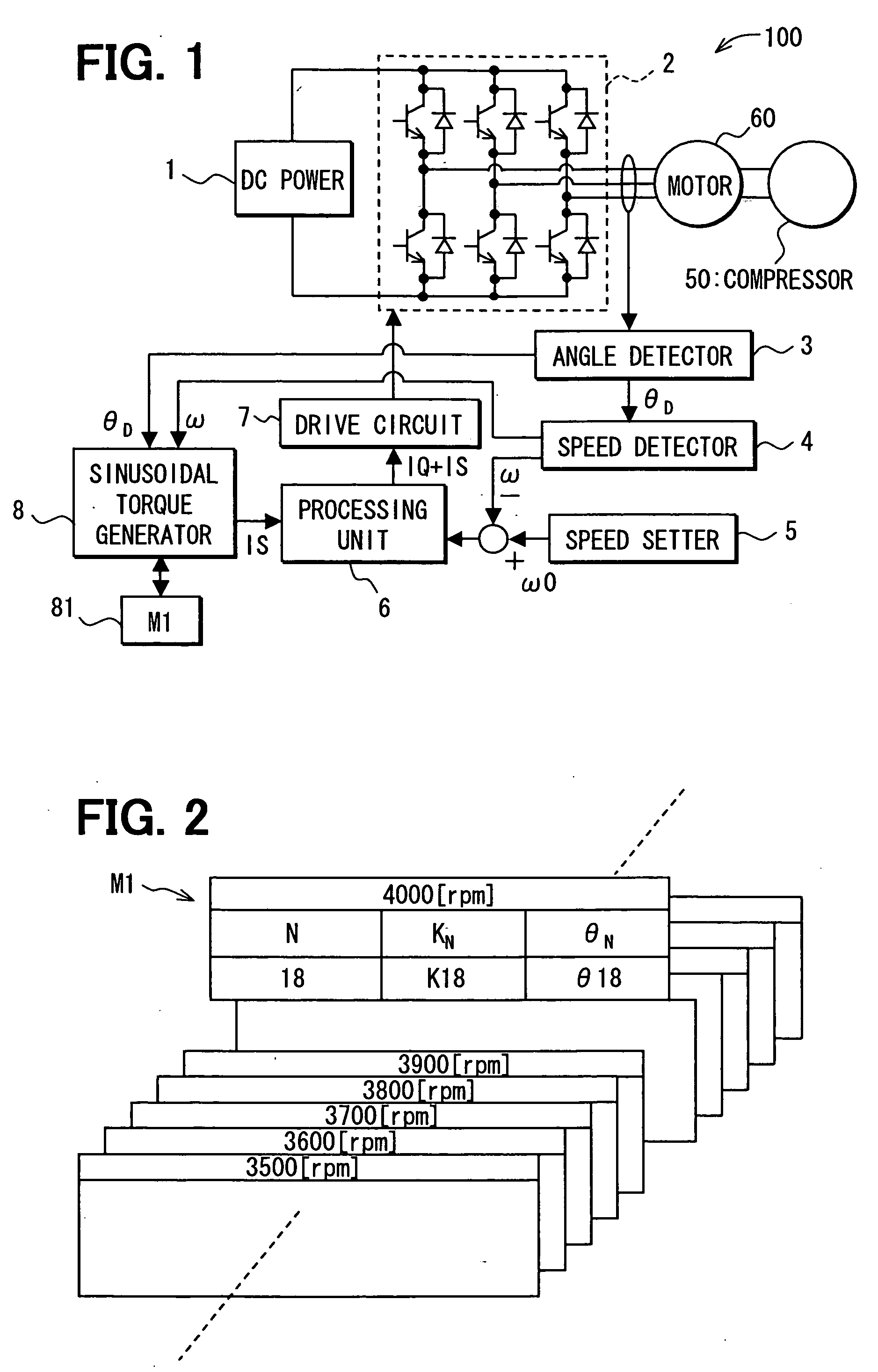
[0029] A motor control apparatus 100 according to the first embodiment of the present invention will now be described with reference to FIGS. 1 to 6.
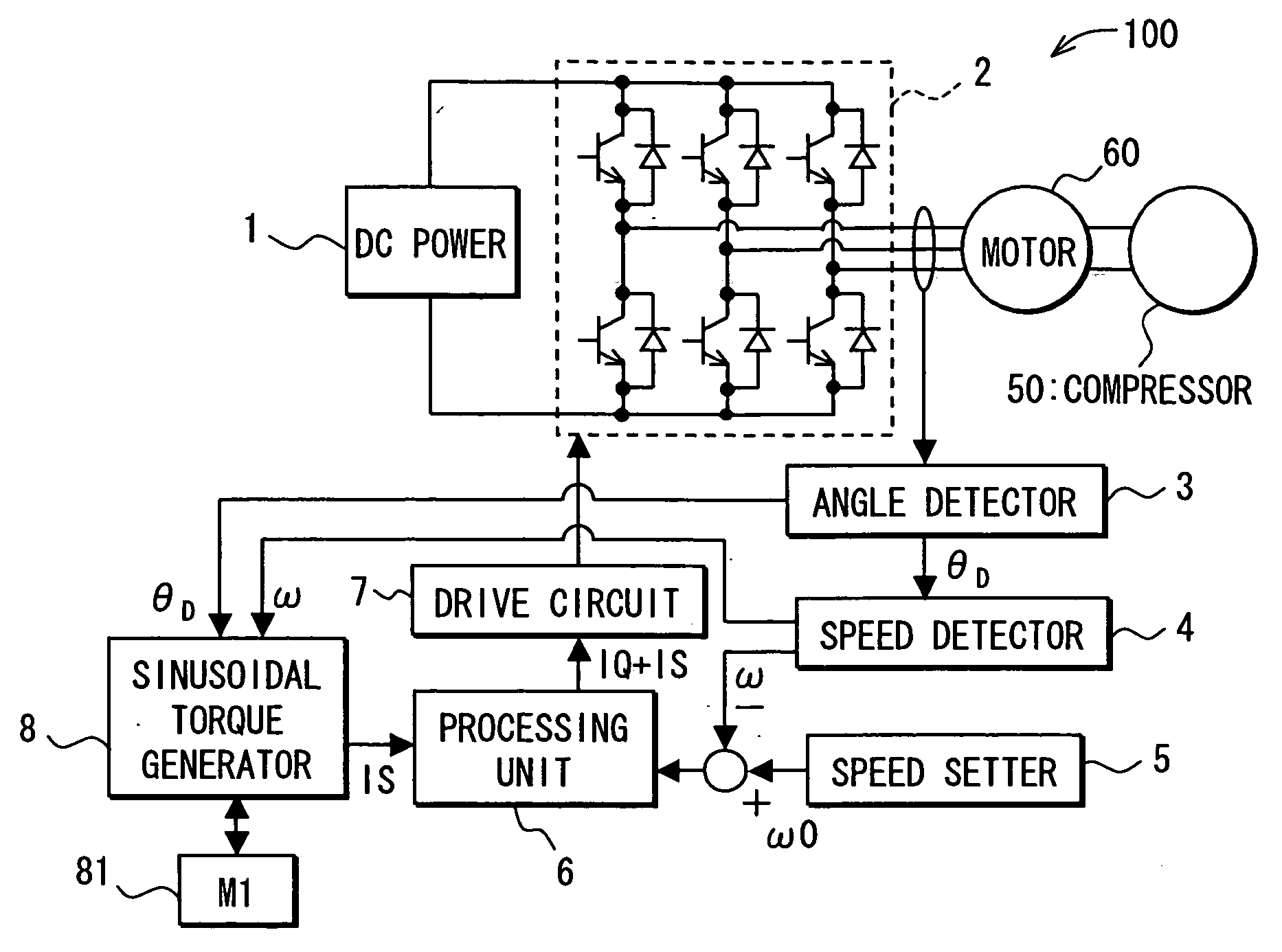
[0030] The motor control apparatus 100 is used to control a motor 60 that drives a compressor 50. The compressor 50 is a component of a vehicular air conditioner unit that uses a refrigeration cycle. In the refrigeration cycle, the compressor 50 pumps refrigerant from an evaporator (not shown), compresses the refrigerant to high temperature and pressure, and supplies the compressed refrigerant to a condenser (not shown). For example, the compressor 50 is mounted to an engine block as a mounting structure in an engine room of a vehicle.
[0031] The motor 60 is a three-phase (phases A-C) brushless direct current (DC) motor and has stator coils corresponding to each of the phases A-C. A voltage is applied to the stator coils at respective timings so that the motor 60 can rotate.
[0032] As shown in FIG. 1, the motor...
second embodiment
[0052] (Second embodiment)
[0053] A motor control apparatus 200 according to the second embodiment of the present invention will now be described with reference to FIG. 7 and FIG. 8.
[0054] In the motor control apparatus 200, a processing unit 6 generates a q-axis voltage signal VQ for allowing the motor 60 to produce the driving torque that follows the ripple in the load torque required to drive the compressor 50. A sinusoidal torque generator 8 receives the rotational speed ω of the motor 60 from the rotational speed detector 4. Then, the sinusoidal torque generator 8 reads the amplitude KN and the phase angle θN corresponding to the order N from the table that is included in the map M1 of the memory 81 and corresponds to the rotational speed ω. Based on the amplitude KN and the phase angle θN, the sinusoidal torque generator 8 generates a sinusoidal voltage signal VS for allowing the motor 60 to produce the sinusoidal torque TS represented by the equation (1). The sinusoidal volta...
third embodiment
[0057] (Third embodiment)
[0058] A motor control apparatus 300 according to the second embodiment of the present invention will now be described with reference to FIG. 9.
[0059] In the motor control apparatus 300, a sinusoidal torque generator 8 generates a sinusoidal rotational speed signal ωS for allowing the motor 60 to produce the sinusoidal torque TS represented by the equation (1). The sinusoidal rotational speed signal ωS and a signal for indicating the desired rotational speed ω0 are combined into a combined speed signal ω0+ωS. As shown in FIG. 9, a deviation signal between the combined speed signal ω0+ωS and a signal for indicating the rotational speed signal o is input to a processing unit 6. The control operation signal 6 generates the q-axis current signal IQ based on the deviation signal and outputs the q-axis current signal IQ to a drive circuit 7. The drive circuit 7 generates the PWM signal based on the q-axis current signal IQ and outputs the PWM signal to the invert...
PUM
 Abstract
Description
Claims
Application Information
 - R&D Engineer
- R&D Manager
- IP Professional
- Industry Leading Data Capabilities
- Powerful AI technology
- Patent DNA Extraction
Browse by: Latest US Patents, China's latest patents, Technical Efficacy Thesaurus, Application Domain, Technology Topic.
© 2024 PatSnap. All rights reserved.Legal|Privacy policy|Modern Slavery Act Transparency Statement|Sitemap