Determination of a model of a geometry of a metal sheet forming stage

Active Publication Date: 2006-12-28
NETABTAL MASCHEN
View PDF5 Cites 27 Cited by
  • Summary
  • Abstract
  • Description
  • Claims
  • Application Information

AI Technical Summary

Benefits of technology

[0077] By way of this, it becomes possible to determine an approximate course of the trailing edge without a complicated separate simulation. A computation and immediate visualisation of the trailing edge in t

Problems solved by technology

The dimensioning and setting of the addendums represents considerable problems today.
It is often the case of an iterative process which entails many reject parts and a high consumption of energy and resources.
The production of addendums nowadays is largely effected in a manual and in an extremely time-consuming manner by way of computer-aided design systems (CAD).
Even the creation of an addendum for a large car body part may take several weeks without further measures.
This initiation is time-consuming and expensive and may last for months.
First, this is

Method used


Image

  • Determination of a model of a geometry of a metal sheet forming stage
  • Determination of a model of a geometry of a metal sheet forming stage
  • Determination of a model of a geometry of a metal sheet forming stage

Examples


Example

[0089] The reference numerals used in the drawings and their significance are listed in a grouped manner in the list of reference numerals. Basically, the same parts are provided with the same reference numerals in the figures.

DETAILED DESCRIPTION OF THE INVENTION

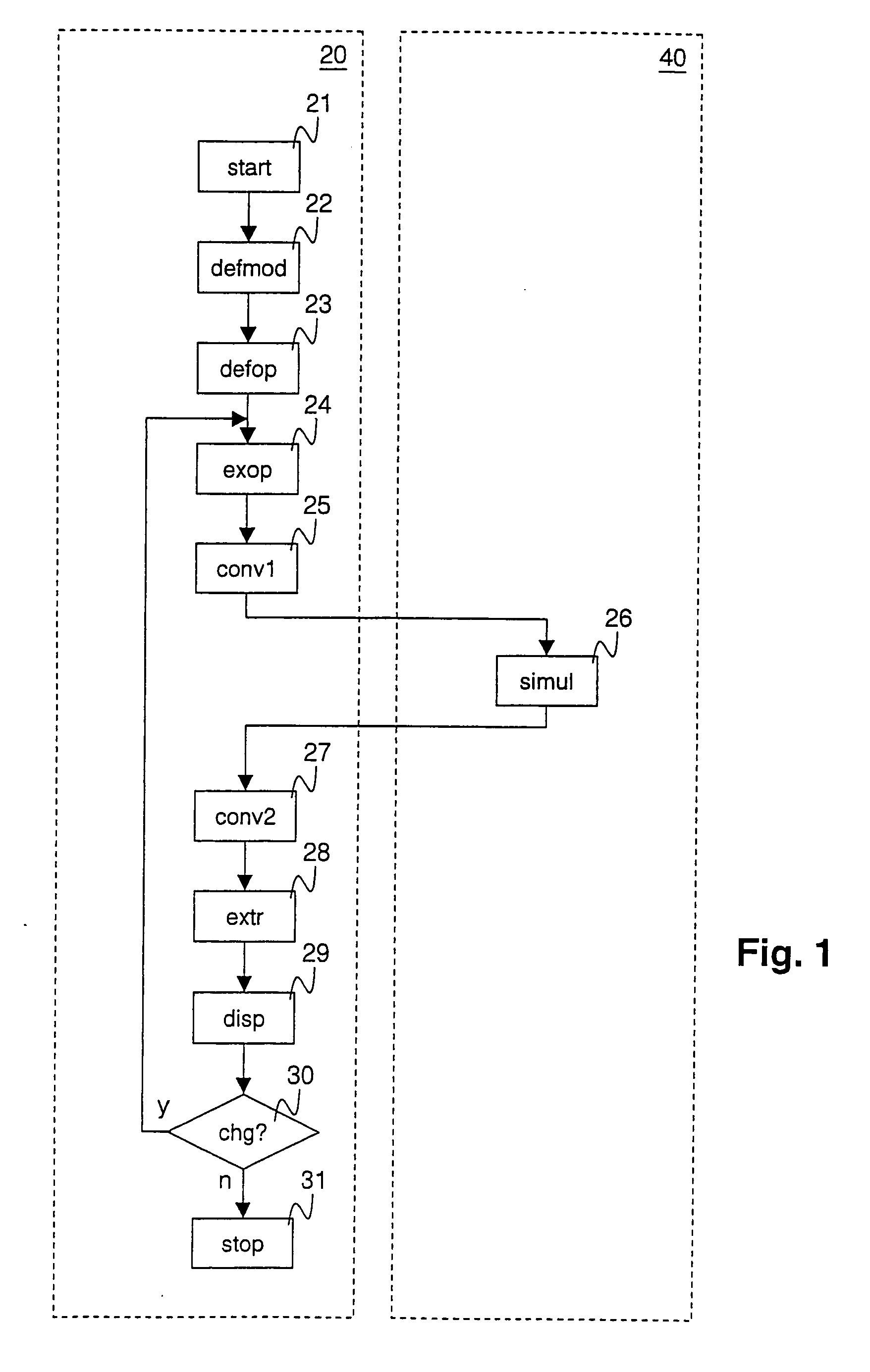
[0090]FIG. 1 shows a procedural course of a method according to the invention. The method runs in a CAD-system 20 for the design of a geometry of forming stages. The method uses functions of a physical simulation system 40 which are either integrated into the CAD-system 20 or are made available via a program interface by way of the physical simulation system 40. A step for model production of a geometry object 22 is carried out after the start 21 of the method within the CAD-system 20. Thereby, the model, for example in the working memory region of a computer, is produced by way of user inputs or by way of stored model data, so that it may be processed by the CAD-system 20. In a step for the definition of an operator 23, ...


PUM


Abstract

The invention relates to a method for determining a geometrical object for modeling the geometry of a metal sheet forming stage (1) in a CAD system. According to said method, an operator is defined which links a first geometrical model with a second geometrical model. The link is associated with a method for physically modeling a treating process which transfers a forming stage (1) from a corresponding first state into a second state. When the first geometrical model is modified, the second geometrical model is automatically updated in accordance with the physical modeling concept. The physical modeling concept for forming stages is thereby integrated into the static geometrical model environment of a CAD system. The physical modeling method is a method for calculating a border line (3) of a forming stage in an initial state prior to a forming process from a geometry of the border line (3) in a resulting state after the forming process.

Description

BACKGROUND OF THE INVENTION [0001] The present invention lies in the field of determining and optimising processing steps on manufacture of sheet metal formed parts, for example by way of deep-drawing or stretch-forming processes. It relates to a method, to a data processing system, to a computer program and to a data carrier for determining a model of a geometry of a forming stage in a computer-aided design (CAD) system, according to the preamble of the respective independent patent claims. [0002] Sheet metal formed parts as a rule are manufactured by way of deep-drawing. The semi-finished product, the so-called sheet metal blanks (or simply “blanks”) are placed into multi-part forming tools for this purpose. The parts are formed by way of presses in which the forming tools are clamped. The parts, as a rule, are manufactured from a flat sheet metal blank via several forming stages by way of machining steps such as drawing, reshaping, setting, etc., combined with trimming steps. Wit...

Claims


Application Information

Patent Timeline
IPC IPC(8): G06F19/00G05B19/4099
CPCG05B19/4099G05B2219/35005G05B2219/35192G05B2219/35016G05B2219/35021G05B2219/35009Y02P90/02
Inventor HILLMAN, MATTHIASKUBLI, WALDEMAR
Owner NETABTAL MASCHEN
Why Eureka
Try Eureka