High energy resolution scintillators having high light output

a scintillator and high light output technology, applied in the field of high energy resolution scintillators, scintillator compositions for high-energy radiation detectors, can solve the problem of high limit of time difference measuremen

Active Publication Date: 2007-01-04
BAKER HUGHES OILFIELD OPERATIONS LLC
View PDF13 Cites 25 Cited by
  • Summary
  • Abstract
  • Description
  • Claims
  • Application Information

AI Technical Summary

Problems solved by technology

The limitations of this time difference measurement are highly dependent on the stopping power, light output, and decay time of the scintillator material.

Method used


Image

  • High energy resolution scintillators having high light output
  • High energy resolution scintillators having high light output
  • High energy resolution scintillators having high light output

Examples


Embodiment Construction

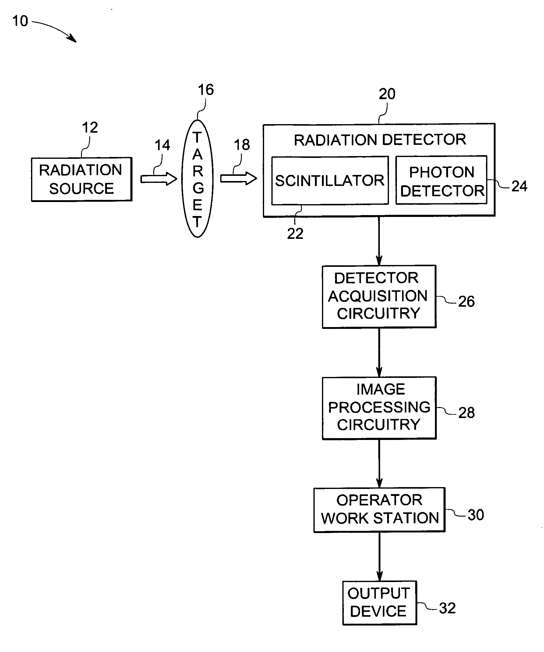
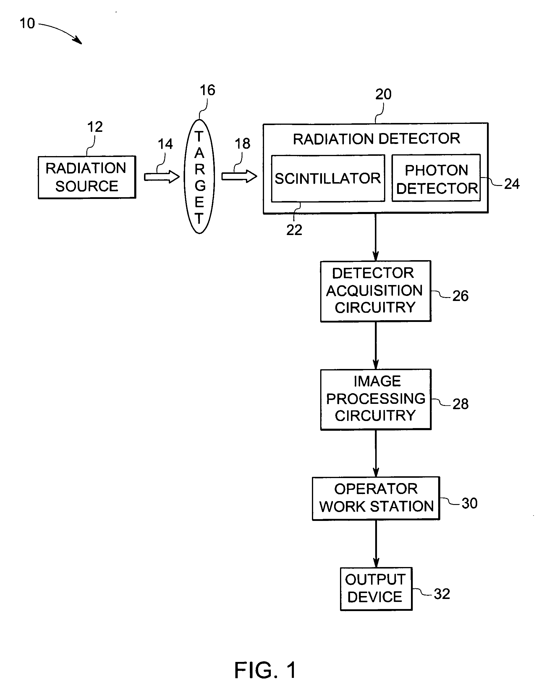
[0018]FIG. 1 illustrates an exemplary radiation-based imaging system, such as a nuclear imaging detector employed in a positron emission tomography, in accordance with certain embodiments of the present technique. In the illustrated embodiment, the imaging system 10 includes a radiation source 12 positioned such that a major portion of the radiation 14 emitted from the radiation source 12 passes through the target 16, such as an animal, or a human, or a baggage item, or any target having internal features or contents. In certain embodiments, the radiation 14 may include electromagnetic radiation, such as X-ray radiation, or beta radiation, or gamma radiation. A portion of the radiation 14, generally termed as attenuated radiation 18, passes through the target16. More specifically, the internal features of the target 16 at least partially reduce the intensity of the radiation 14. For example, one internal feature of the target 16 may pass less or more radiation than another internal ...


PUM

PropertyMeasurementUnit
mole percentageaaaaaaaaaa
wavelengthaaaaaaaaaa

Abstract

A scintillator composition includes a matrix material, where the matrix material includes an alkaline earth metal and a lanthanide halide. The scintillator composition further includes an activator ion, where the activator ion is a trivalent ion. In one embodiment, the scintillator composition includes a matrix material represented by A2LnX7, where A includes an alkaline earth metal, Ln includes a lanthanide ion, and X includes a halide ion. In another embodiment, the scintillator composition includes a matrix material represented by ALnX5, where A includes an alkaline earth metal, Ln includes a lanthanide ion, and X includes a halide ion. In these embodiments, the scintillator composition includes an activator ion, where the activator ion includes cerium, or bismuth, or praseodymium, or combinations thereof.

Description

BACKGROUND [0001] The invention relates generally to the field of imaging systems and, more particularly, to scintillator compositions for use in high-energy radiation detectors. [0002] High-energy radiation based imaging systems, such as positron emission tomography (PET), generally employ a scintillator detector having a plurality of pixels typically arranged in a circular array. Each such pixel comprises a scintillator cell coupled to a photomultiplier tube. In PET, a chemical tracer compound having a desired biological activity or affinity for a particular organ is labeled with a radioactive isotope that decays by emitting a positron. Subsequently, the emitted positron interacts with an electron giving out two 511 keV photons (gamma rays). The two photons emit simultaneously and travel in almost exactly opposite directions, penetrate the surrounding tissue, exit the patient's body, and become absorbed and recorded by the detector. By measuring the slight difference in arrival ti...

Claims


Application Information

Patent Timeline
Patent Type & Authority Applications(United States)
IPC IPC(8): G01T1/20
CPCC09K11/7705C09K11/7773C04B35/5152C04B2235/3206C04B2235/3229C04B2235/3213C04B2235/3215C04B2235/3224C04B2235/3225C04B2235/3208
Inventor SRIVASTAVA, ALOK MANIDUCLOS, STEVEN JUDECLARKE, LUCAS LEMARCOMANZO, HOLLY ANNDENG, QUN
Owner BAKER HUGHES OILFIELD OPERATIONS LLC
Why Eureka
Try Eureka