Cushion material formed of spring-structured resin-molded product, manufacturing method for the cushion material, and mold used for the manufacturing method

a technology of spring structure and resin molded products, which is applied in the field of cushion materials composed of resin molded articles, can solve the problems of difficult to obtain a product of which parts are modified in density and strength, unstable balance, fatigue, etc., and achieves the effects of easy production, simple molding process, and excellent shock resistance and load resistan

Inactive Publication Date: 2007-01-04
AIN ENJINIARINGU
View PDF4 Cites 35 Cited by
  • Summary
  • Abstract
  • Description
  • Claims
  • Application Information

AI Technical Summary

Benefits of technology

[0018]“The continuous and / or short filaments” may be solid or hollow. If the continuous and / or short filaments are hollow, they are preferable because the air is entrapped in the hollow cavities of the filaments, and act as a spring which confers a characteristic spring property to the filaments. The air entrapped in the hollow cavities of the filaments also prevents the collapsing tendency of the filaments which would otherwise result from long and habitual use. The air entrapped in the hollow cavities of the filaments also preserves the rigidity of the three-dimensional structure. The hollow cavities may be continuous with other ones or may be independent of each other. As one illustrative example, each of single hollow fibers may have hollow cavities with septa inserted between adjacent cavities. If a mixture of solid filaments and hollow filaments is used as a material of the filaments, the mixture ratio of solid filaments to hollow filaments is preferably solid:hollow=0 to 50:50 to 100. Further, if hollow filaments are used in a central portion of the structure, and covered with solid ones, the resulting structure will give a desirable tactile impression.
[0024] The “female die” is preferably made of concrete. The concrete die dispenses with the use of a separating agent, and thus reduces the cost of molding. The “male die” preferably consists of a product (base) to which the cushion material can be attached. Then, need for separate preparation of a male die can be safely avoided, which will allow the molding cost to be reduced, and precision of molding to be improved. Cooling may consist of spontaneous cooling or forced cooling. Forced cooling is preferably based on the use of water.
[0025] The cushion material of the invention is more receptive to secondary processing than polyurethane, and can respond to needs from consumers with regard to particular functions more finely than polyurethane. Molding the cushion material is achieved by compression molding. Thus, it is possible to provide a product to match with the body shape of a given user, or in accordance with the order of a user which will further enhance the advantage of the product. Moreover, by adjusting the diameter of filaments constituting a resin molded article with a spring structure, material of the filaments, and their denier, bulk density and void ratio, it is possible to allow the resin molded particle to have a desired spring property. Although individual filaments constituting the cushion material of the invention are equal in terms of spring property, they may be conferred different spring properties after having been differently compressed during compression molding. Therefore, it is possible to provide a cushion material in which different portions have different cushioning abilities and thus in which, when a weight is put thereon, the weight is supported in different manners according to the sites with which it is put into contact. Moreover, it is possible by adjusting the stroke of the male die to allow the mold to have a desired thickness.
[0026] Particularly, the “male die” may be constituted with a base (which forms an element of the cushion material constituting the product) to which a resin molded article with a spring structure can be attached. Then, deliberate preparation of a male die dedicated for the purpose can be safely dispensed with, which will lead to the reduced production cost. Moreover, because part of the product is used as an element (molding part) of the molding apparatus, precision of molding will be improved. For raising or lowering the male die, it is preferable to use a pantograph type framework. As compared with a hydraulic cylinder or pneumatic cylinder which is used in a conventional apparatus for molding polyurethane, the framework in question is so simple that it will contribute to the reduction of production cost as well as to the simplification of production facilities. The male die is preferably so constructed as to forbear a load weighing it or more. If the female die is made of concrete, it will be possible to safely dispense with the use of a separating agent which would be otherwise required, as well as to reduce production cost as compared with molding where metal dies are used for the same purpose. Moreover, since the molding process itself is simplified, and time required for molding is contracted, mass production of cushion materials will become possible. Cooling may consist of spontaneous cooling or forced cooling. Forced cooling is preferably based on the use of water.
[0027] Generally speaking, with regard to the resin molded article with a spring structure as described above, ends of the article tend to disintegrate after molding, and thus require trimming or rounding-off subsequent to molding, which may be cumbersome. However, with the present article with a spring structure, it is possible to trim ends of the article after compression molding by cutting and fusion using a heat cutter, and thus to dispense with the trimming process as above, which reduces superfluous works.

Problems solved by technology

Thus, his balance becomes unstable, and he gets fatigued if he sits on the seat for a long time.
With this manufacture it is difficult to obtain a product of which parts are modified in density and strength according to the functions they are assigned.
Furthermore, because polyurethane foam is so soft and elastic that, when man rests his weight on a seat made of polyurethane foam, he feels an upward thrust on his buttock, touching on a hard bottom, and vertical swing, and his feet may become numb and strongly tired if he rests on the seat for a long time.
Demands with regard to the manufacture and structure of such a polyurethane seat are manifold, but the material itself is so uniform in density that, when a man sits on the seat, the distribution of pressures on the sitting surface changes from moment to moment, and thus polyurethane foam may not be suitable according to given functions assigned to the seat.
Therefore, it is difficult for the product of polyurethane foam to change its spring properties in accordance with given requirements.
As it is, because the seat cannot change its spring property according to the type of motor cycle or to the rider's posture, the rider must put or lift his weight on or off the seat as needed during racing, which, when repeated often over a long time, will cause the overall center of gravity to be elevated and unbalanced.
Further, it is difficult to recycle polyurethane foams since they are thermosetting resins.
Therefore, polyurethane foams can only be recycled by crushing them into chips with a crusher, and bonding the chips into a material called chip foam (ribbon dead foam), or can only be burned for recovery of thermal energy.
However, stable lands cannot be created by using polyurethane foams since they are low in bulk density and soft, and hence landfill sites suitable therefor are limited.
Polyurethane foams may be processed into particles or powders to be disposed which requires, however, extra handling and costs.
Further, incineration of polyurethane foams may generate hydrocyanic acid gases (hydrocyanic acid) which cause much damage to incinerators, and have to be eliminated at high costs.
As described above, it is difficult to dispose polyurethane foams in accordance with the Recycle Act without giving adverse side effects on environments during and after disposal.
In addition to above, polyurethane foams have problems as described below.
The separation process is complicated and molding time is long.
It is difficult to clean polyurethane foams.
This is because an amine catalyst used during manufacture is trapped in the foams, causing bad smell.
A polyurethane foam has a heat storage property, and is liable to be stuffy, and there is a fear that if the polyurethane foam is exposed to intensive light for a long time, it may start to burn.
Its safety to environments is low.
Although year 2020 is set to a deadline of abolition of use of CFCs (chlorofluorocarbons) substitute which is used as a foaming agent, there is not yet found an alternate agent that is more excellent in foaming performance than the CFCs substitute.
In many actual manufacturing sites, thorough control of TDI is not carried out, causing damage to health of workers.
In the cushion structure proposed in the Japanese Patent No. 2548477, it is difficult to be recycled due to fusing polyester fibers with a high melting point via a thermoplastic elastomer with a low melting point, resulting in complicated manufacturing method and high cost for producing.
Although the cushion proposed in Japanese Laid-Open Patent Publication (Kokai) No. 2000-51011 offers advantages in that it has excellent air permeability and is cleanable, it suffers from disadvantages in that it has a low durability, a manufacturing method thereof is complicated, and a processing cost is remarkably high.
Further, since the rubber adhesive and a crosslinkable polyurethane are thermoset resins, and the cushion is not of a single composition, it is difficult to recycle the cushion.
At present, however, despite that polyurethane foams have many problems as described above, there is no alternate agent to replace polyurethane that can be used not less suitably and cheaply than polyurethane as a cushion material of the seats of automotive vehicles, motor cycles, bicycles, electric trains, and aircraft, and of beds.

Method used


Image

  • Cushion material formed of spring-structured resin-molded product, manufacturing method for the cushion material, and mold used for the manufacturing method
  • Cushion material formed of spring-structured resin-molded product, manufacturing method for the cushion material, and mold used for the manufacturing method
  • Cushion material formed of spring-structured resin-molded product, manufacturing method for the cushion material, and mold used for the manufacturing method

Examples


Embodiment Construction

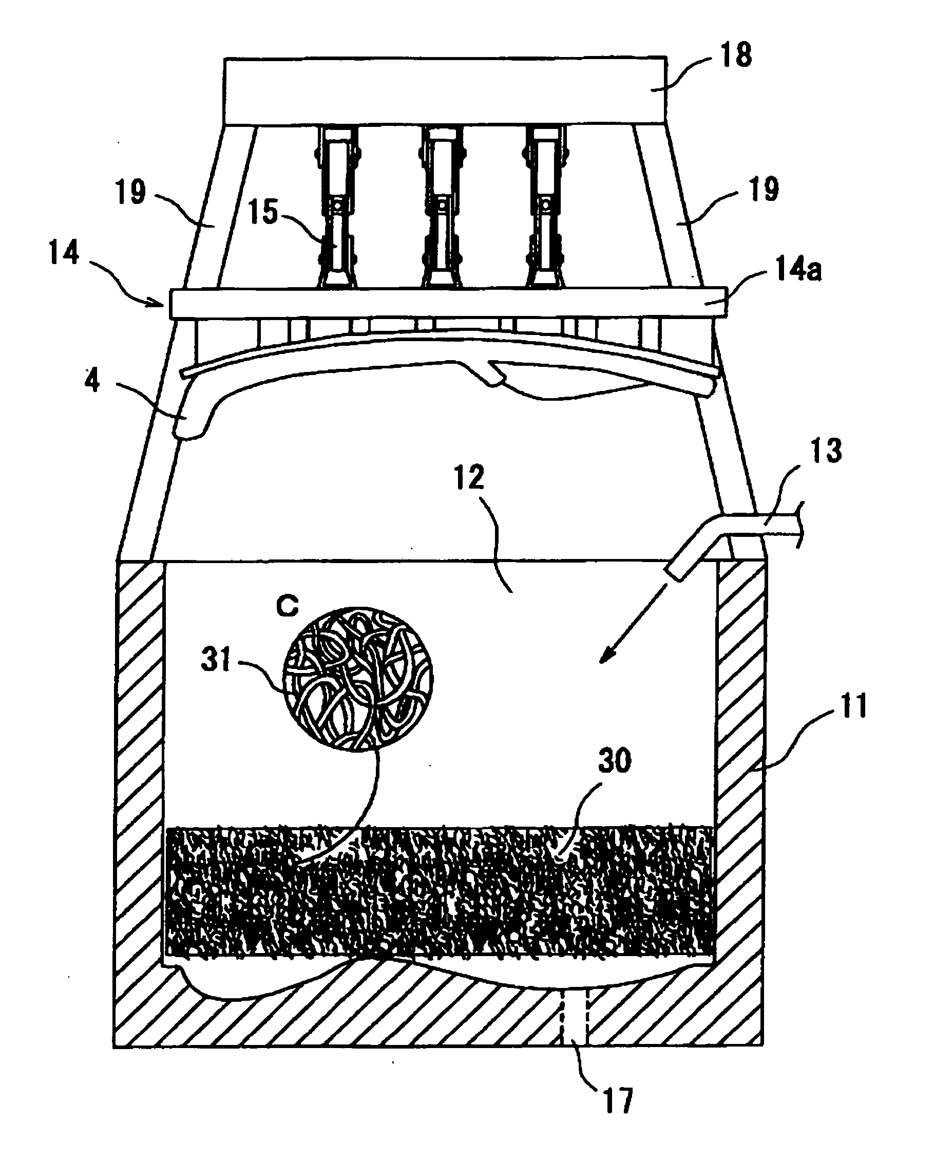
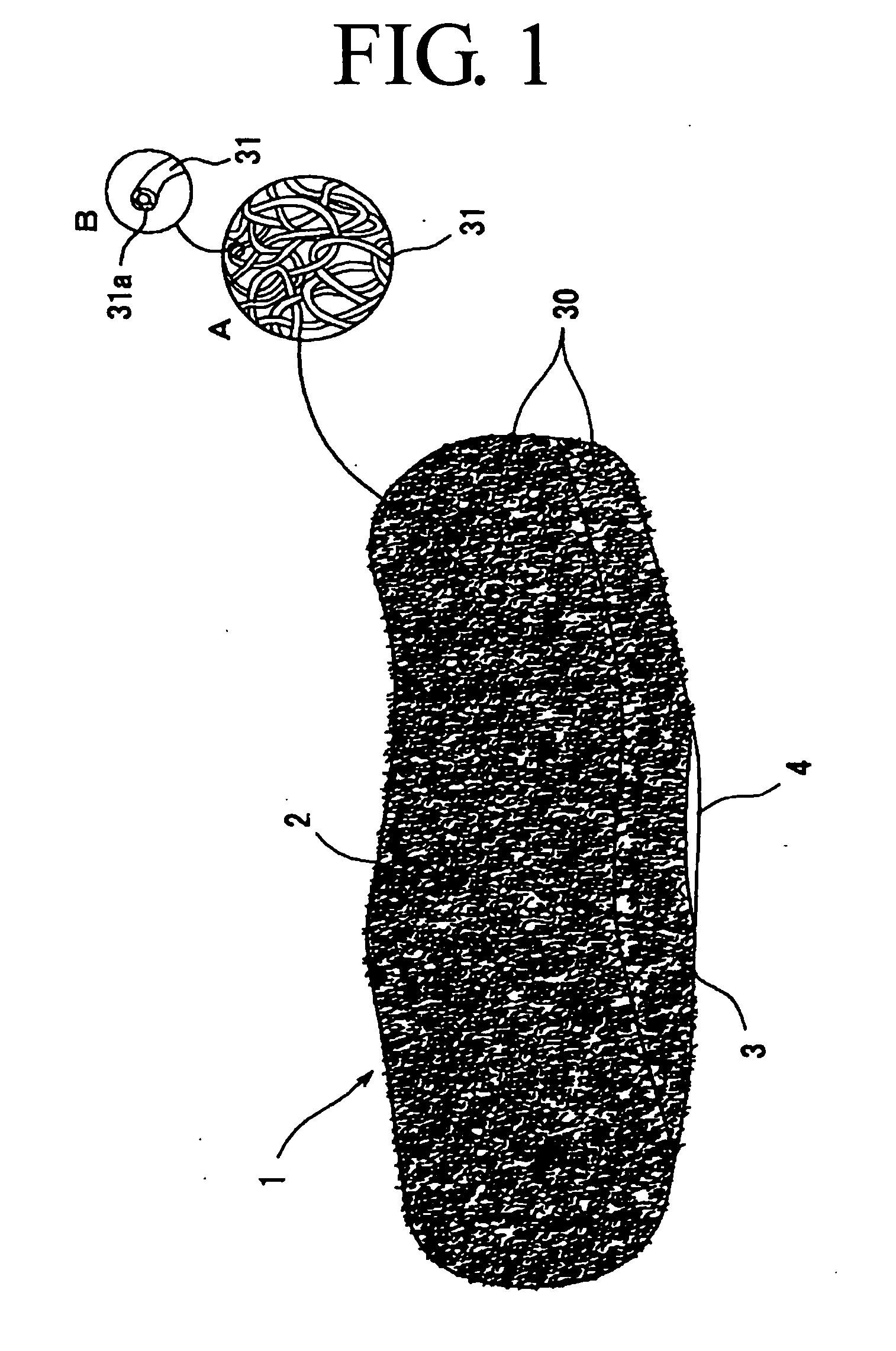
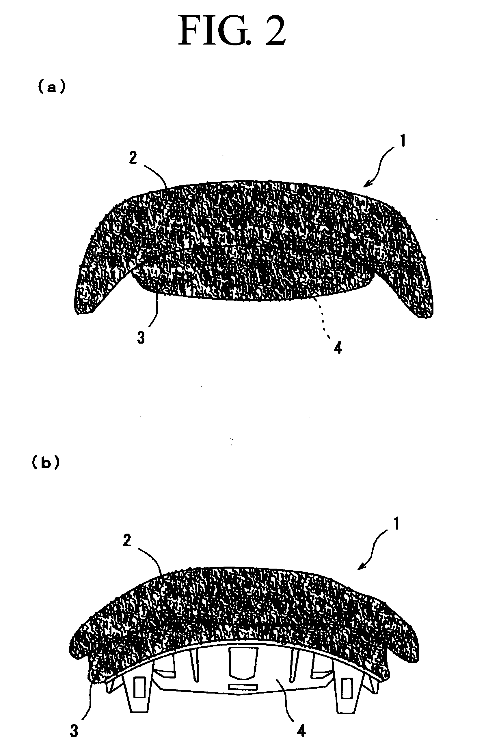
[0055] As is obvious from the reference to a perspective view shown in FIG. 1, and frontal and rear views shown in FIGS. 2a and 2b, the cushion material 1 is obtained by preparing a thermoplastic resin (e.g., thermoplastic elastomer) such as a blend obtained by mixing, for example, a polyolefin resin such as PE, PP, etc., with VAC, EVA or SBS, and by processing the blend into a resin molded article 30 with a spring structure or a three-dimensional structure, and subjecting the article or the structure to compression molding.

Explanation of a Resin Molded Article 30 with a Spring Structure

[0056] Firstly, the resin molded article 30 with a spring structure will be described.

[0057] The resin molded article 30 with a spring structure used in this embodiment of the invention is a three-dimensional structure having voids which is obtained by contacting, entwining, and gathering adjacent ones of random loops or curls of continuous and / or short filaments (simply filaments 31 hereinafter)...


PUM

PropertyMeasurementUnit
diameteraaaaaaaaaa
diameteraaaaaaaaaa
densityaaaaaaaaaa

Abstract

There is provided a method for producing a cushion material composed of a resin molded article with a spring structure which is so moldable as to allow the mold take any shape and size, is cheap, and resistant to collapsing, does not cause fatigue even after prolonged use, and has high shock absorbing capability and load capacity, and thus suitably used as a material of any supports on which one can sit, rest or mount such as seats of automotive vehicles, motor cycles, bicycles, electric trains, and aircraft, saddles for horse riding, chairs, sofas and beds, and a method for producing a cushion material requiring only a low cost for its disposal.

Description

BACKGROUND OF THE INVENTION [0001] 1. Technical Field [0002] The present invention relates to a cushion material composed of a resin molded article having a spring structure, method of producing the same, and dies used in manufacture of the cushion material, more particularly to a method for producing a resin molded article with a spring structure which is excellent in shock resistance and load capacity, and has an ability to meet specific and non-specific needs in terms of shape and size in various industrial fields, that is, a material suitably used for producing any supports on which one can sit, rest or mount such as seats of automotive vehicles, motor cycles, bicycles, electric trains, and aircraft, saddles for horse riding, chairs, sofas and beds, and to a method for producing a cushion material which requires a low cost and burden for its disposal, and low production cost by simplifying production facilities, and improves the precision of molding, and apparatuses necessary fo...

Claims


Application Information

Patent Timeline
Patent Type & Authority Applications(United States)
IPC IPC(8): D21J3/00A47C27/12B62J1/18B62J1/26D04H1/00
CPCA47C27/12A47C27/122D04H3/037B62J1/26D04H3/16B62J1/18
Inventor NISHIBORI, SADAOKOBAYASHI, TATSUMISHIRAI, MAKINAKAMURA, YUICHIRO
Owner AIN ENJINIARINGU
Why Eureka
Try Eureka