
Systems and Methods for Ramping Power Amplifier Output Power

a power amplifier and output power technology, applied in the direction of high-frequency amplifiers, transmission, gain control, etc., can solve the problems of undesirable harmonics affecting other channels in the frequency band, affecting the efficiency of power output adjustment, and emitted undesirable harmonics. , to achieve the effect of minimizing the emission of undesirable harmonics and efficient adjustment of power outpu

Active Publication Date: 2007-01-04
AVAGO TECH INT SALES PTE LTD
View PDF7 Cites 3 Cited by
  • Summary
  • Abstract
  • Description
  • Claims
  • Application Information

AI Technical Summary

Benefits of technology

[0010] Broadly speaking, the present invention fills these needs by providing a system and method of efficiently adjusting the power output of a portable transmitter in a manner that substantially minimizes emission of undesirable harmonics. It should be appreciated that the present invention can be implemented in numerous ways, including as a process, an apparatus, a system, computer readable media, or a device. Several inventive embodiments of the present invention are described below.

Problems solved by technology

An important source of unwanted emissions is an abrupt change in output power level.
When the transmitted power output abruptly transitions either upward or downward, undesirable harmonics of the selected channel frequency can be emitted.
The undesirable harmonics can interfere with other channels in the frequency band.
By way of example, if a transmitter is abruptly turned off (or on), undesirable harmonics can be emitted.

Method used


Image

  • Systems and Methods for Ramping Power Amplifier Output Power
  • Systems and Methods for Ramping Power Amplifier Output Power
  • Systems and Methods for Ramping Power Amplifier Output Power

Examples


Embodiment Construction

[0039] Several exemplary embodiments systems and methods of efficiently adjusting the power output of a portable transmitter in a manner that substantially minimizes emission of undesirable harmonics will now be described. It will be apparent to those skilled in the art that the present invention may be practiced without some or all of the specific details set forth herein.

[0040] One embodiment provides a system and method for adjusting an output power of a portable transmitter for the specific conditions of use (e.g., location, proximity to corresponding receiver). The power output can be adjustable over a selected power range and with a selected resolution. By way of example, if two transceivers are too close together, one transceiver can tell the other transceiver to reduce its power output for power equalization or even optimization over a given distance (i.e., proximity). The system and method for adjusting the output power can also be used on other types (i.e., non-portable t...


PUM


Abstract

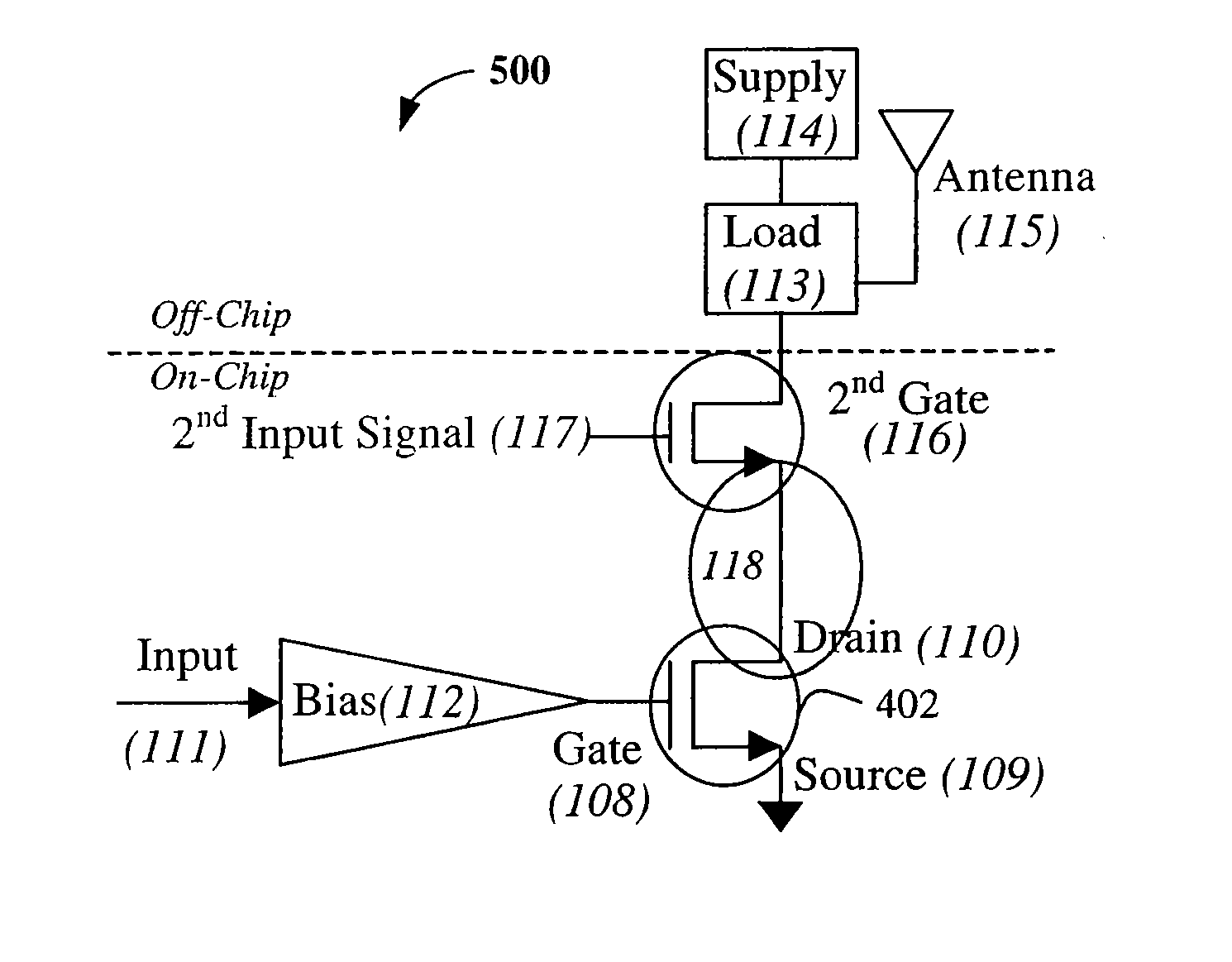
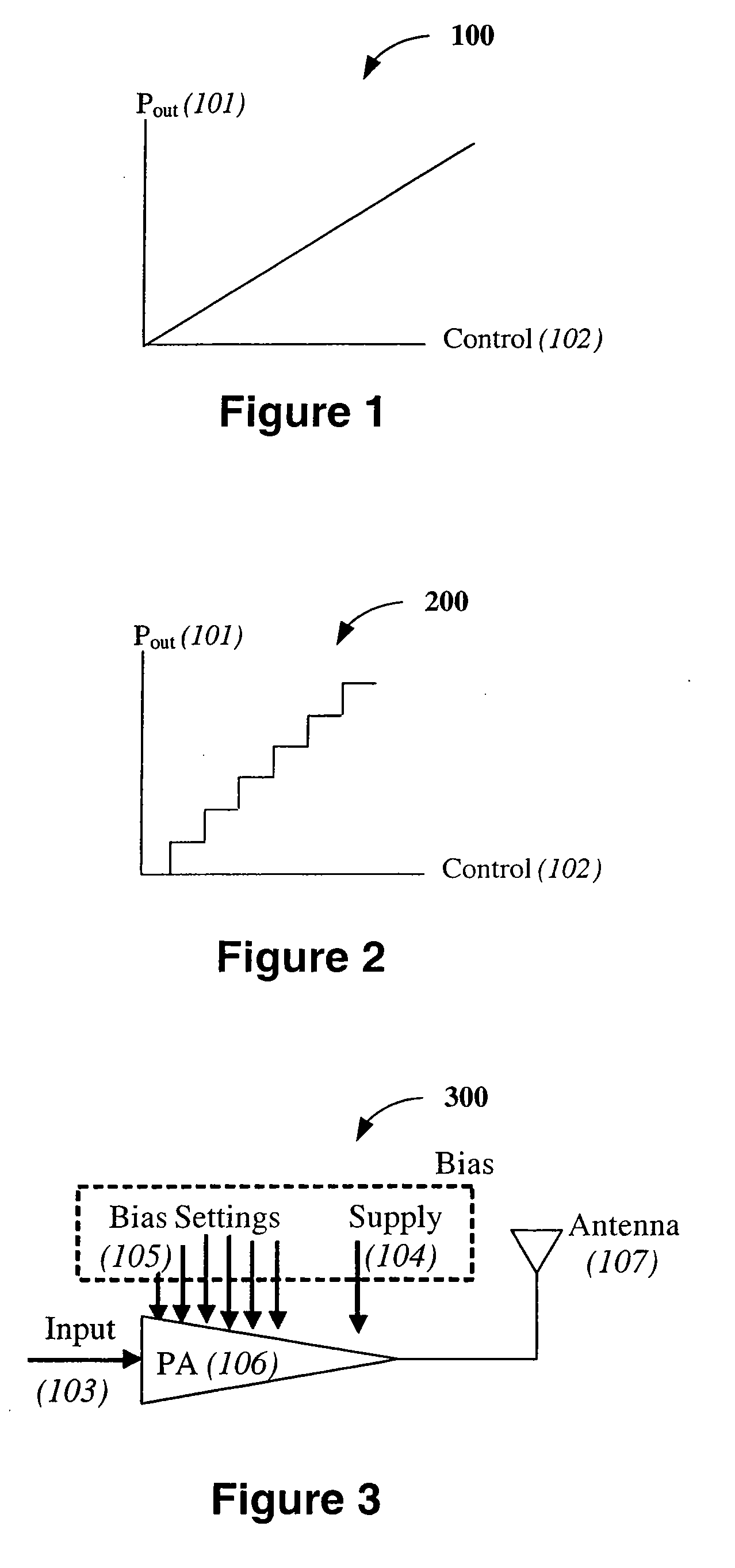
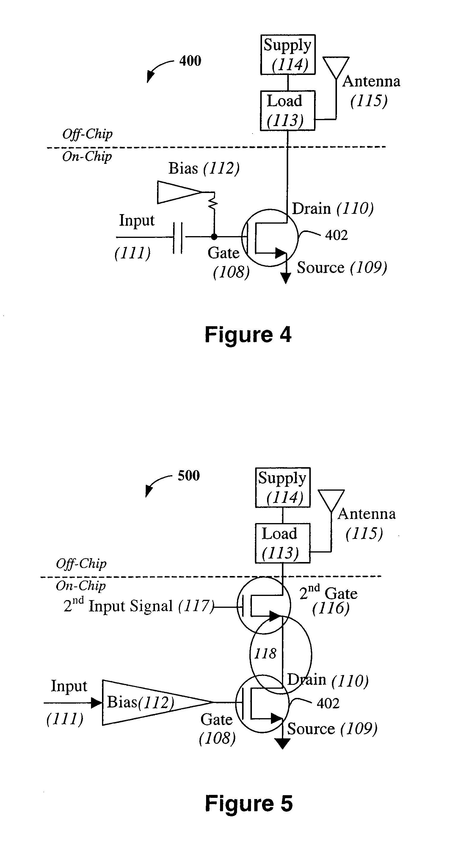
A power amplifier circuit including a first transistor, a second transistor, and a power control circuit. The first transistor includes a first input and a first output. The second transistor includes a second input coupled in series with the first output of the first transistor. The input circuit is coupled to the second input of the second transistor. The control circuit includes a time delay circuit and a variable source.

Description

CROSS REFERENCE TO RELATED APPLICATIONS [0001] This application claims priority from U.S. Provisional Patent Application No. 60 / 463,955 filed on Apr. 18, 2003 and entitled “Systems and Methods for Ramping Power Amplifier Output Power,” which is incorporated herein by reference in its entirety.BACKGROUND OF THE INVENTION [0002] 1. Field of the Invention [0003] The present invention relates generally to power amplifier circuits, and more particularly, to methods and systems for controlling the output power of a power amplifier circuit. [0004] 2. Description of the Related Art [0005] Portable transmitting devices are becoming more and more common, led first by the popularity of cellular telephones and increasingly by wireless networking products such as under the “Bluetooth” and IEEE 802.11 type (802.11) specifications. Two requirements of these types of products is a small physical size and efficient, long term (e.g., multiple days') operation relying on only battery power source. Ano...

Claims


Application Information

Patent Timeline
Patent Type & Authority Applications(United States)
IPC IPC(8): H03G3/10
CPCH03F1/0205H03F1/0261H03F1/223H03F3/19H03G3/004H03F2200/18H03F2200/451H03G1/0023H03F3/24
Inventor NILSON, CHRIS
Owner AVAGO TECH INT SALES PTE LTD
Learn More