Method for manufacturing semiconductor device

a manufacturing method and semiconductor technology, applied in the direction of electrical equipment, instruments, computing, etc., can solve the problems of reducing reliability and yield of wireless chips, cracks easily caused by glass substrates, end portions and corners of substrates, etc., and achieve high reliability and high yield

Inactive Publication Date: 2007-01-04
SEMICON ENERGY LAB CO LTD
View PDF6 Cites 9 Cited by
  • Summary
  • Abstract
  • Description
  • Claims
  • Application Information

AI Technical Summary

Benefits of technology

[0018] Since a semiconductor device of the present invention has a cross section (hereinafter, it may be referred to as “edge face”) of the substrate, of which a thickness is thinner than 100 μm (preferably, 2 μm or more and 50 μm or less), having curvature, chipping and crack from an edge face of a substrate can be prevented from occurring. As a result, a semiconductor device having flexibility and high reliability, which can endure

Problems solved by technology

In this dividing step, there is a problem of causing lack (hereinafter, referred to as “chipping”) in an end portion and a corner of the substrate.
The problem is particularly remarkable in a case where a substrate

Method used


Image

  • Method for manufacturing semiconductor device
  • Method for manufacturing semiconductor device
  • Method for manufacturing semiconductor device

Examples


embodiment mode 1

[0033] In the present embodiment mode, an example of a structure of a method for manufacturing a semiconductor device of the present invention will be described with reference to drawings.

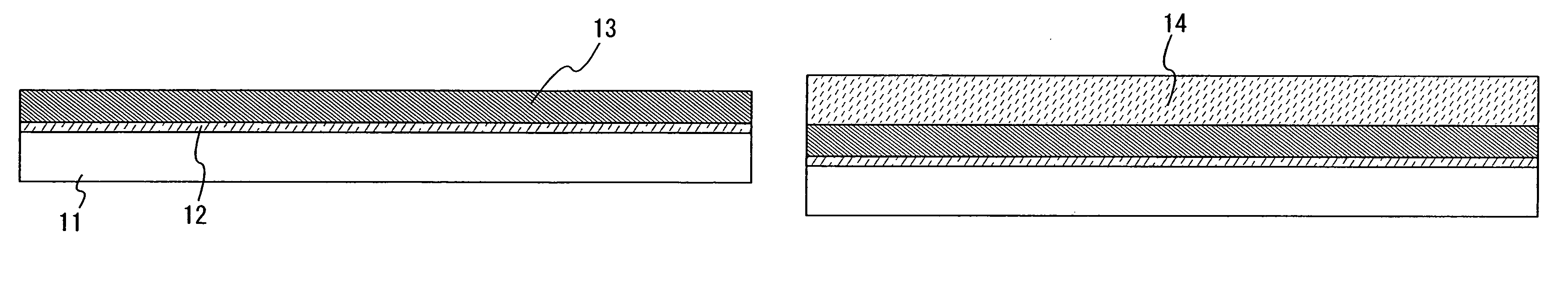
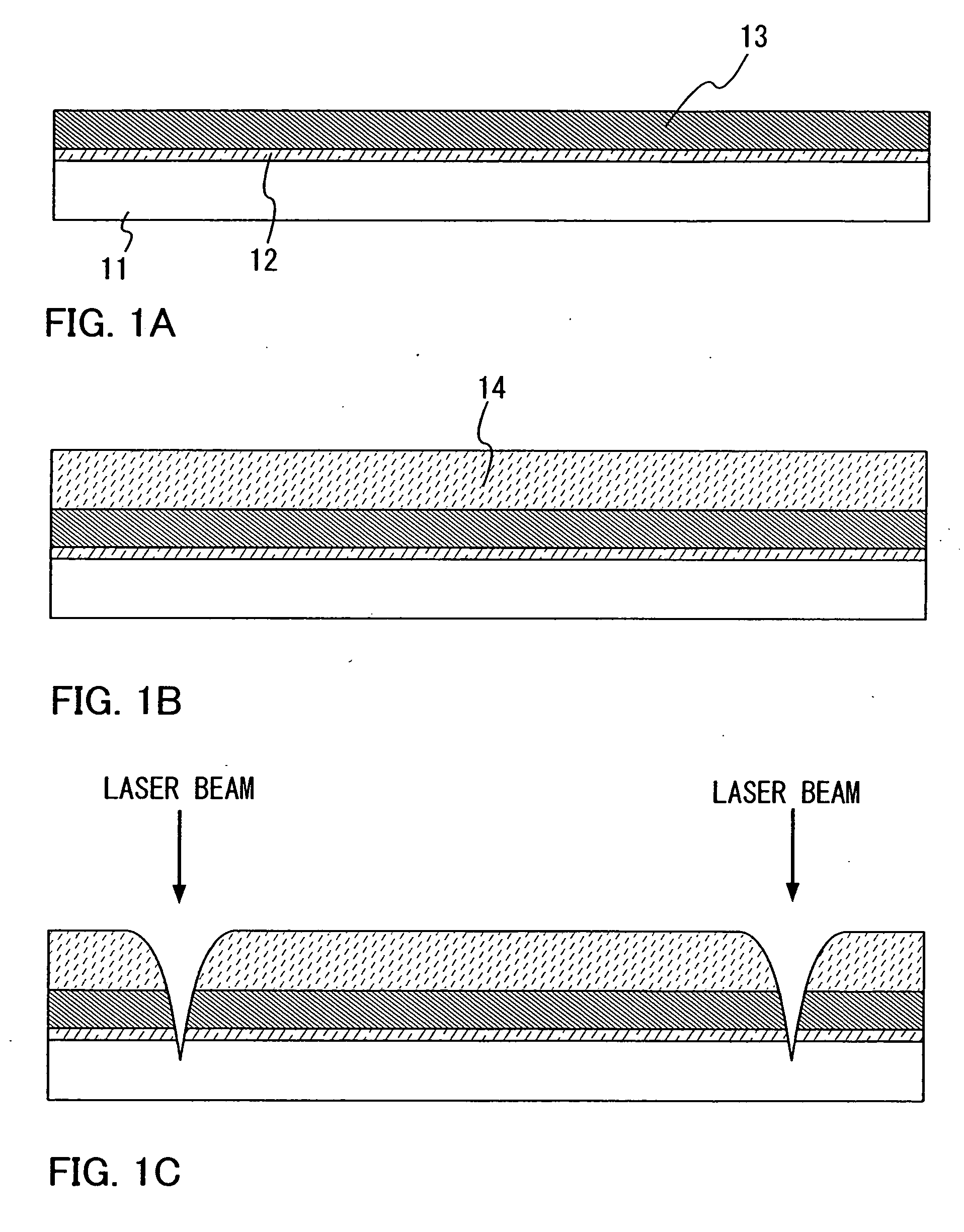
[0034] First, a base film 12 is formed over one surface of a substrate 11 (FIG. 11A). When pollution from the substrate is concerned, the base film 12 is preferably formed over the substrate 1; however, the base film 12 is not always necessary to be provided. It is to be noted that “one surface of the substrate 11” indicates a surface of a side provided with the base film 12 and an element layer 13 formed afterward in the present specification.

[0035] The substrate 11 can be made of glass, quartz, silicon, metal, ceramic, stainless, plastic, acryl, or the like. However, a glass substrate is preferably used. When a glass substrate is used, an area and a shape thereof are not limited particularly. Therefore, in a case of using a glass substrate as the substrate 11, it is possible to easily use a rec...

embodiment mode 2

[0065] In the present embodiment mode, a method for manufacturing a semiconductor device of the present invention including a thin film transistor and an antenna will be described with reference to drawings. In particular, a structure of an element layer will be described in detail.

[0066] First, a base film 703 is formed over a substrate 701 (FIG. 5A). As a material and a forming method of the substrate 701 and the base film 703, the material and the forming method described in Embodiment Mode 1 can be used; therefore, the description is omitted here.

[0067] Next, an amorphous semiconductor film 704 (for example, a film containing mainly amorphous silicon) is formed over the base film 703. The amorphous semiconductor film 704 is formed by a sputtering method, various types of a CVD method such as a plasma CVD method or the like to have a thickness of 25 to 200 nm (preferably, 30 to 150 nm). Subsequently, the amorphous semiconductor film 704 is crystallized to form a crystalline sem...

embodiment mode 3

[0117] In the present embodiment mode, a method for forming an antenna that is different from the method described in Embodiment Mode 2. In other words, in the Embodiment Mode 2, the structure where the antenna is formed as a part of the element layer is described; however, in the present embodiment mode, a substrate provided with an antenna is prepared differently, and a structure where the substrate provided with the antenna and a substrate provided with an element layer are attached with each other will be described.

[0118] First, as described in Embodiment Mode 2, up to the conductive film 763 is formed over the substrate 701 (FIG. 6B). The steps up to forming the conductive film 763 are described in Embodiment Mode 2; therefore, the description thereof is omitted here.

[0119] Next, a substrate 781 provided with an antenna 782 and the substrate 701 provided with the element layer are attached with each other (FIG. 8). In FIG. 8, as a means for attachment, an anisotropic conducti...


PUM


Abstract

It is an object of the present invention to provide a method for manufacturing a semiconductor device, which is flexible and superiority in physical strength. As a method for manufacturing a semiconductor device, an element layer including a plurality of integrated circuits is formed over one surface of a substrate; a hole having curvature is formed in part of one surface side of the substrate; the substrate is thinned (for example, the other surface of the substrate is ground and polished); and the substrate is cut off so that a cross section of the substrate has curvature corresponding to a portion where the hole is formed; whereby a laminated body including an integrated circuit is formed. Further, a thickness of the substrate, which is polished, is 2 μm or more and 50 μm or less.

Description

BACKGROUND OF THE INVENTION [0001] 1. Field of the Invention [0002] The invention disclosed in the present specification relates to a method for manufacturing a semiconductor device. The present invention particularly relates a method for manufacturing a semiconductor device capable of communicating data by wireless communication. [0003] 2. Description of the Related Art [0004] In recent years, a semiconductor device capable of communicating data by wireless communication has been actively developed. Such a semiconductor device is called an IC tag, an ID tag, an RF (Radio Frequency) tag, an RFID (Radio Frequency Identification) tag, a wireless tag, an electronic tag, a wireless processor, a wireless memory, a wireless chip, or the like (for example, see Japanese Patent Application Laid-Open No. 2004-282050). [0005] A wireless chip is generally constituted by an antenna and an IC chip, and the IC chip is formed of an element layer including a transistor or the like provided over a si...

Claims


Application Information

Patent Timeline
IPC IPC(8): H01L21/00
CPCG06K19/07749
Inventor TSURUME, TAKUYAKUSUMOTO, NAOTO
Owner SEMICON ENERGY LAB CO LTD
Why Eureka
Try Eureka