
Suture anchor with improved torsional drive head

a technology of torsional drive head and suture anchor, which is applied in the field of suture anchors, can solve the problems of permanent damage to the drive head, inability to achieve torque transfer, and inability to reduce the low stripping strength

Inactive Publication Date: 2007-01-04
DEPUY MITEK INC
View PDF20 Cites 75 Cited by
  • Summary
  • Abstract
  • Description
  • Claims
  • Application Information

AI Technical Summary

Problems solved by technology

While conventional suture anchors and their drivers are sufficient, they have some drawbacks.
Anchor heads with hexagonal or square shaped cross-sections, for example, tend to have a relatively low stripping strength, meaning that under relatively small torque loads the drive head is permanently damaged and torque transfer is thus inhibited.
Additionally, this low stripping strength can be further reduced due to the structural integrity of the anchor head, whose drive interface has been compromised or weakened to some degree by the incorporation of a suture attachment element such as an eyelet used to attach the suture to the anchor head.
If the head shape of an attachment element decreases the amount of material on the anchor drive head that interfaces with the driver, then the amount of material that needs to yield or be “stripped” from the drive head is reduced, thus reducing the stripping strength of the head.
Conventional suture anchor heads also tend to have a relatively low failure torque, which can result in shearing off of the drive head during insertion.
In suture anchors, this failure may be exacerbated by the location of the suture attachment element in the head.
In particular, if a loop is molded into and embedded within the anchor such that the loop extends outward from the head of the anchor to receive a suture, the entire drive head is relatively weakened and thus has the potential to shear off during insertion.
Suture anchors were historically constructed of implantable metals and alloys which afforded sufficiently high tensile and torsional strength to withstand the rigors of insertion, but the implant remained in the body for prolonged periods of time.
Polymer, ceramic, or composite material systems, both biodegradable and non-biodegradable, have been developed for similar applications, but typically have lower tensile and torsional strength than metal counterparts, thus increasing the risk of device failure during application of high torque loads during insertion, as described above.
These filled systems may have further reduced tensile or torsional properties compared to unfilled polymer systems.
Large anchor heads, however, require a large driver tool, which in turn requires a relatively large tunnel to be formed in the bone.
This is particularly undesirable, especially where the tunnel is to be formed in the cancellous bone, and where the procedure is minimally invasive and must traverse through a cannula or arthroscope.
Accordingly, most suture anchors are adapted for use with a relatively small driver tool, and thus have relatively small drive heads which can result in a low failure torque and a low stripping strength, particularly in harder bone applications.
Deformation may cause distortion of the anchor near the suture attachment regions, which can inhibit suture slideability necessary to afford knot tying.

Method used


Image

  • Suture anchor with improved torsional drive head
  • Suture anchor with improved torsional drive head
  • Suture anchor with improved torsional drive head

Examples


example 1

Insertion Torque to Failure Tests

[0053] Suture anchors with the drive head of the design in FIG. 7 consisting of two ARM's, each approximately 0.050″ in height and width, aligned in the plane of the suture eyelets, were subjected to insertion torque to failure tests versus a similar design without the two ARMs. Anchors were machined out of polysulfone.

[0054] Torque to failure tests were conducted in solid rigid polyurethane foam blocks (Sawbones, 1522-02, Pacific Research Laboratories, Inc., Vashon, Wash.). Torque measurements were recorded in inch-pounds using an Imada (Imada, Inc., Northbrook, Ill.) model DSD-4 Digitial Torque Tester / Screwdriver with mating ¼″ hexagonal drive Jacobs chuck attachment. The mean torque to failure of five anchors with ARMs was 7.0 in-lbs compared to 5.6 in-lbs for anchors designs without ARM's, representing a 25% increase in torque capacity of the drive head due to the present invention (ARM's) in polysulfone.

example 2

Insertion Torque to Failure Tests

[0055] Suture anchors with the drive head of the design in FIG. 6 consisting of two ARM's, each approximately 0.125″ in height and 0.050″ in width, aligned in the plane of the suture eyelets, were subjected to insertion torque to failure tests versus a similar design without the two ARMs and with the eyelets reversed, thus having the most distal eyelet traverse the long axis of the oval head while the proximal eyelet traverses the short axis of the oval head. Anchors were injection molded from a 30 / 70 by weight beta-TCP / (85 / 15 poly(lactide) / poly(glycolide) composite material (starting Inherent Viscosity of raw polymer approximately 3.0 dl / g measured in chloroform (CHCl3) using the Cannon Automated Viscometer).

[0056] Torque to failure tests were conducted in solid rigid polyurethane foam blocks (Sawbones, 1522-02, Pacific Research Laboratories, Inc., Vashon, Wash.) under approximately a 6-10 lb compressive load. Torque measurements were recorded in ...


PUM


Abstract

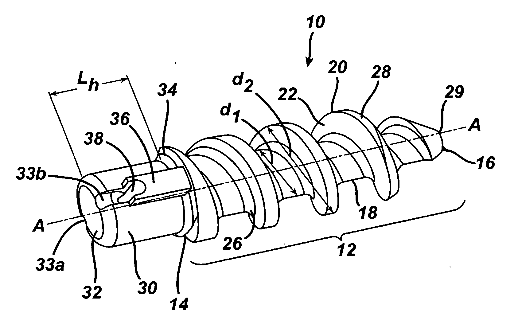
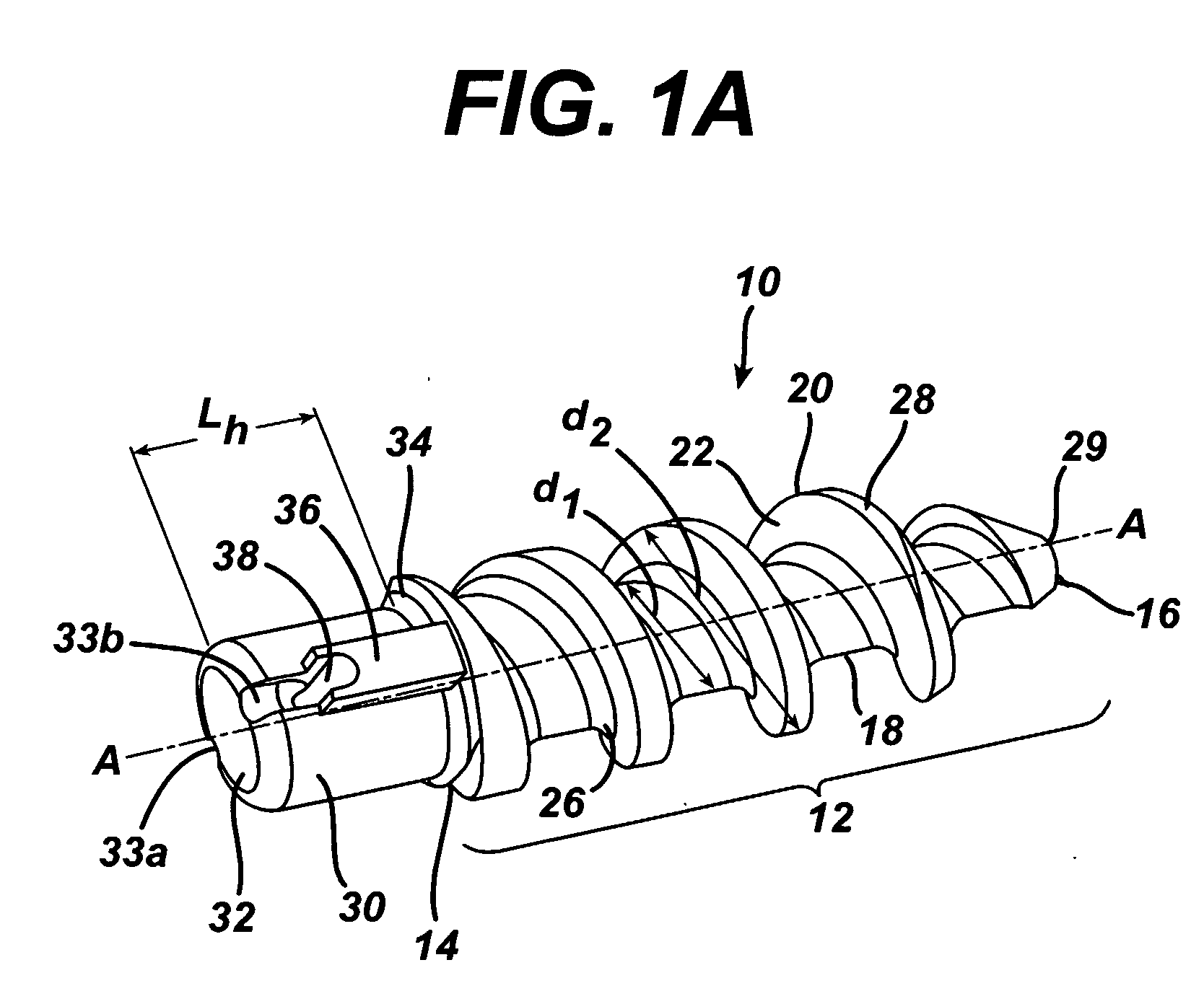
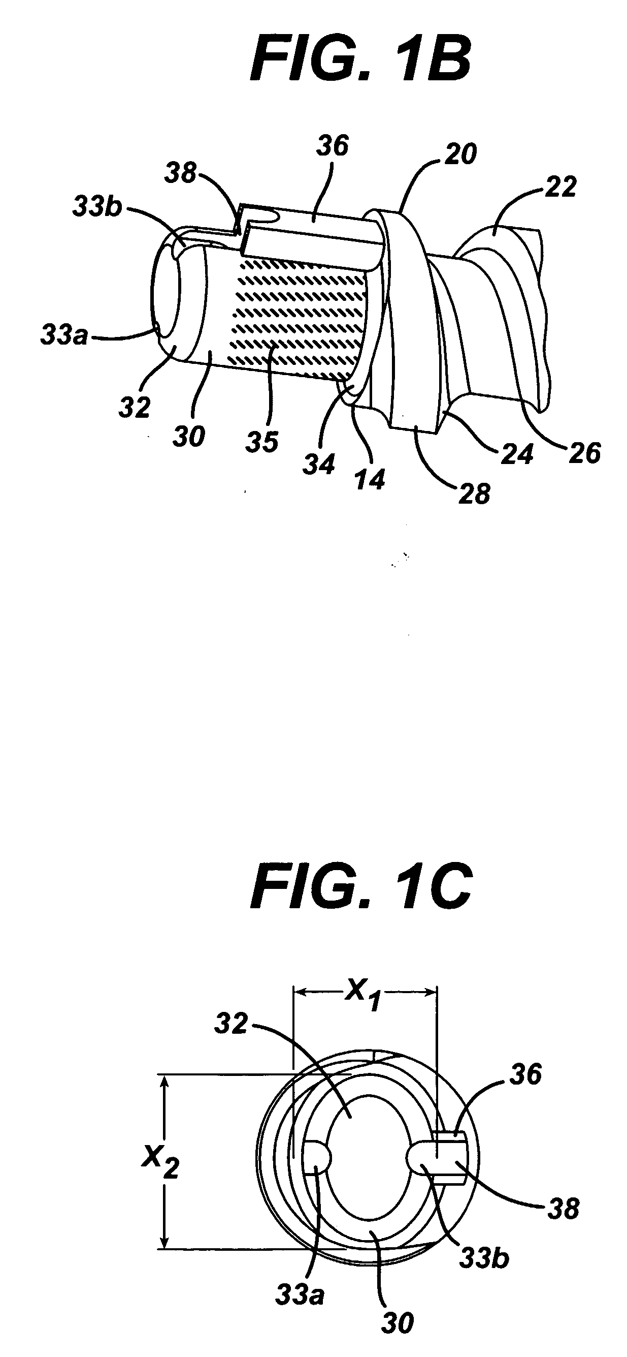
The present invention provides a suture anchor that includes an elongate shank defining a longitudinal axis and having at least one engaging member for applying the suture anchor within the bone and securing the suture anchor in the bone once implanted formed thereon, and a drive head having a proximal end, a distal end and a radial cross-sectional geometry, where the drive head is mated to the elongate shank, includes at least one suture attachment element formed in a portion thereof and at least one anti-rotational member integral therewith, suture anchor kits utilizing the suture anchors and methods of attaching bone to gone.

Description

FIELD OF THE INVENTION [0001] The present invention relates to suture anchors having improved physical properties, more particularly, to biologically compatible suture anchors requiring torsional forces to secure their application within body tissue. BACKGROUND OF THE INVENTION [0002] Suture anchors are often used to attach a length of suture to bone in order to use the suture to secure detached soft tissue to the bone. Suture anchors typically have an anchor body, a suture attachment element, and a bone-engaging member for facilitating placement and retaining the suture anchor within bone. The anchor can be inserted into a preformed hole in the bone, and / or the anchor can be self-tapping and thus can include threads for securing the anchor within bone. Oftentimes suture anchors require the application of torsional forces from an insertion tool at one end of the anchor to drive the suture anchor into bone, as with screw-type anchors. Insertion tools are typically formed from an elon...

Claims


Application Information

Patent Timeline
IPC IPC(8): A61B17/58
CPCA61B17/0401A61B2017/00004A61B2017/044A61B2017/0412A61B2017/0414A61B2017/0409
Inventor CONTILIANO, JOSEPH H.LI, YUFULI, ZHIGANGCAULDWELL, NATHAN
Owner DEPUY MITEK INC
Learn More