Satellite dish antenna mount

Inactive Publication Date: 2007-01-11
RACK FACTORY
View PDF24 Cites 32 Cited by
  • Summary
  • Abstract
  • Description
  • Claims
  • Application Information

AI Technical Summary

Benefits of technology

[0014] Preferably the hollow base, the cylindrical mount and the support post are all formed of a polymeric material structure, such as polyvinyl chloride or other generally rigid polymer structure having material properties that allow the machining and cutting thereof. Similarly, the pivoting mechanism fixing the support post alignment relative the cylindrical mount also comprises non-magnetic components, the non-ferrous assembly therefore allowing use of an inexpensive magnetic compass to assist in the orientation of the base along a predetermined azimuth. In this manner the induced magnetic distortion errors that are usually associated with unwanted distortions of the local magnetic field are wholly avoided. This cooperative structural arrangement is further simplified by way of a threaded extension of the mounting post into a domed ball surface captured between a cap on the end of the cylindrical mount by a helical spring and a dished surface within the cylinder opposing the threaded extension or the post so that a partial turn thereof then provides the frictional interlock to fix its generally vertical alignment as determined by the bubble level seated in the free end of the post. A satellite dish antenna, conventionally provided with elevation adjustment, can then be fixed to the mounting post along the azimuth referenced to the compass.
[0015] One will appreciate that the planform of th

Problems solved by technology

In each instance either the physical burden of various in-ground or overhead cables or the width of the useable electromagnetic spectrum have limited the number of available programming sources.
Thus either the

Method used


Image

  • Satellite dish antenna mount
  • Satellite dish antenna mount
  • Satellite dish antenna mount

Examples


Embodiment Construction

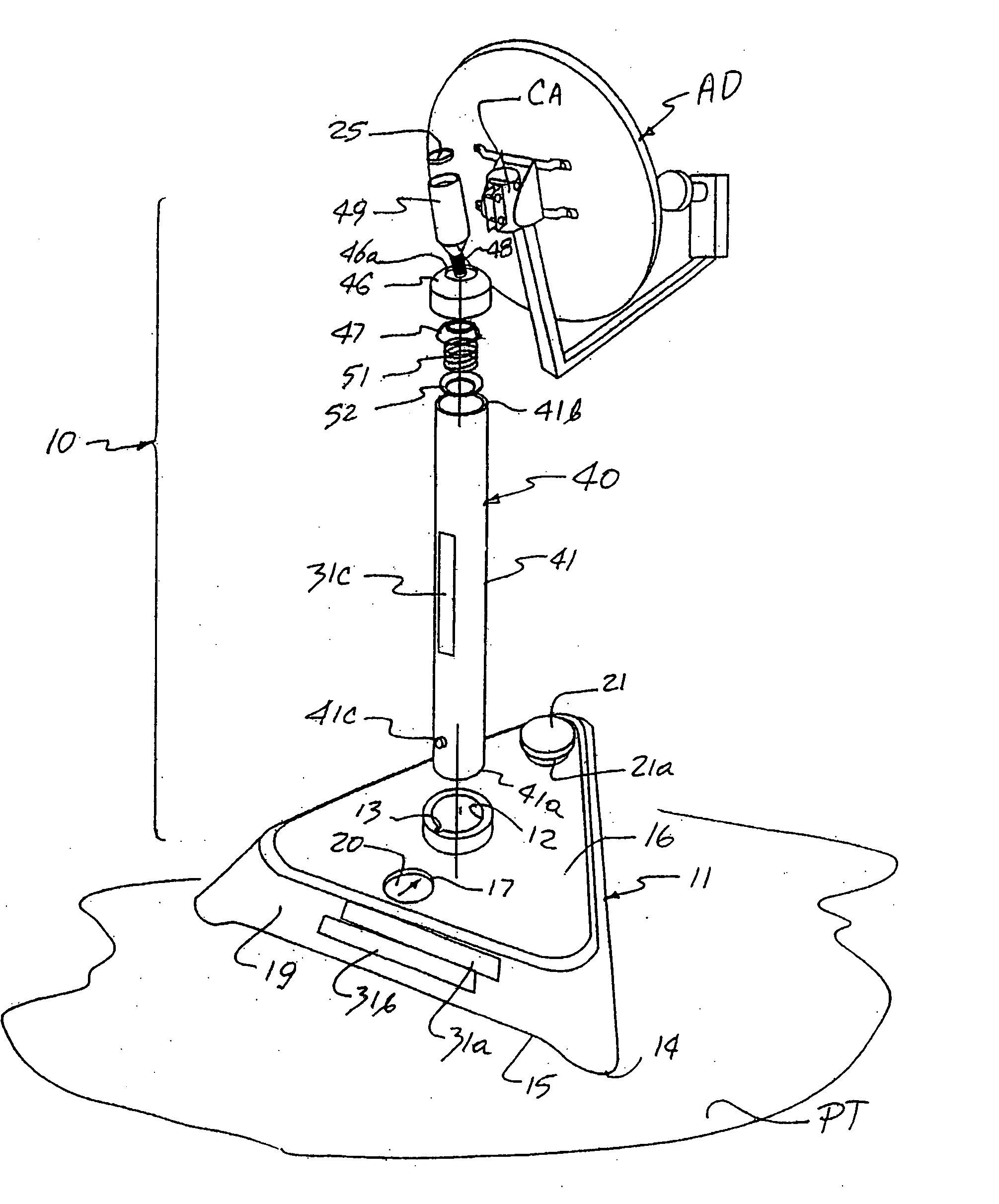
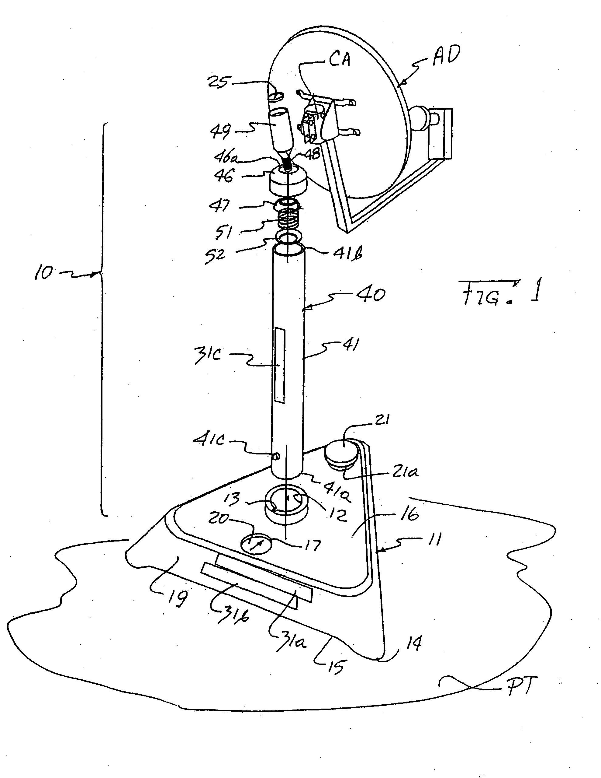
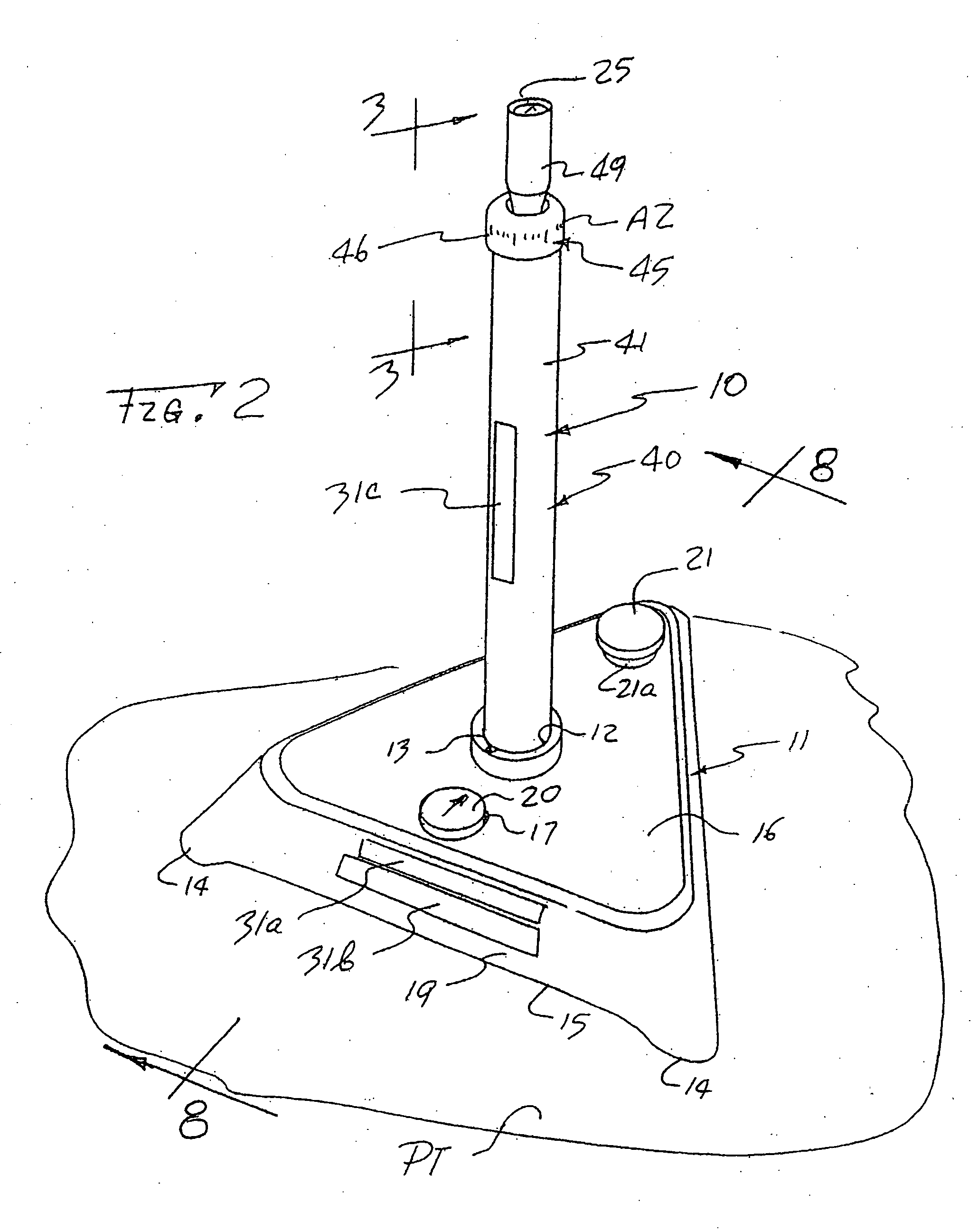
[0027] As shown in FIGS. 1 through 5, the inventive antenna mount assembly, generally designated by the numeral 10, includes a hollow base container 11 of a generally triangular planform provided with a vertically aligned circular annulus 12 radially deformed to include a keyway 13, thus forming a triangular enclosure supported on pads 14 along its bottom surface 15 at each apex of the triangle. The upper surface 16 of the container 11, in turn, is provided with a circular depression 17 conformed for fitted receipt of a magnetic compass 20 adjacent one rear panel 19 of the container which further includes in opposed alignment at the distally opposite apex a fill opening 21a closed by a threaded cap 21, thus forming an enclosure into which water can be selectively admitted to weigh down the base and thereafter drained out before transport.

[0028] The generally elongate rear surface 19 may also serve as a storage panel for the other components of the assembly 10, including the storage...


PUM


Abstract

In an array of cooperating parts useful to form a portable satellite dish antenna mount base an assortment of attachments is provided to secure the base to a marina storage box, structural elements of a stabilized recreational vehicle and also to ground. At the same time the interface between the base and the mount itself may be tapered along interfering tapers to render the assembly and disassembly convenient. Once assembled an end mounting post on the mount is aligned to a vertical alignment with the assistance of a bubble level in the post end to support the dish antenna thereon. The base may further include a magnetic compass to aid in the antenna alignment.

Description

REFERENCE TO RELATED APPLICATION [0001] This application is a continuation-in-part of U.S. patent application Ser. No. 10 / 306,278 filed on Nov. 27, 2002, now U.S. patent ______ and of U.S. design patent application Ser. No. 29 / 189,455 filed on Sep. 5, 2003. The benefits of these earlier filing dates are claimed for all matter common therewith.BACKGROUND OF THE INVENTION [0002] 1. Field of the Invention [0003] The present invention relates to satellite dish antenna mounts, and more particularly to a conveniently transported mount assembly useful to combine into a dish antenna mount that may be generally fixed at various selected orientations. [0004] 2. Description of the Prior Art [0005] The transmission of television and other similar signals has gone through several evolutions, first in the form of broadband radio signal then followed by various land lines or cable networks. In each instance either the physical burden of various in-ground or overhead cables or the width of the usea...

Claims


Application Information

Patent Timeline
IPC IPC(8): A45D19/04F16M11/00F16M11/14F16M13/02H01Q1/12
CPCF16M13/02F16M2200/08H01Q1/1235F16M11/22F16M11/00F16M11/14H01Q1/125
Inventor DIERKES, BARRY
Owner RACK FACTORY
Why Eureka
Try Eureka