Laser scanning microscope and image acquiring method of laser scanning microscope

a laser scanning microscope and scanning microscope technology, applied in the field of laser scanning microscopes, can solve the problems of affecting the illumination effect of the sample, the focusing position is slightly deviated, etc., and achieve the effect of reducing the deviation in the focusing position

Active Publication Date: 2007-01-11
EVIDENT CORP
View PDF15 Cites 28 Cited by
  • Summary
  • Abstract
  • Description
  • Claims
  • Application Information

AI Technical Summary

Benefits of technology

[0011] A laser scanning microscope according to another aspect of the present invention includes a light source that generates a multiwavelength laser beam containing plural wavelengths; a wavelength extracting unit that extracts a laser beam with one or more wavelength from the multiwavelength laser beam; an objective lens that focuses the laser beam on a sample; an optical scanning unit that two-dimensionally scans the sample by the laser beam; a first focusing position control unit that is provided on an optical path of the laser beam, and shifts a focusing position of the laser beam on the sample in a direction of an optical axis of

Problems solved by technology

Furthermore, the sample might not be ideally illuminated with an illuminating light due to the aberration.
On the other hand, there is a problem that a focusing position is slightly deviated in a direction of

Method used


Image

  • Laser scanning microscope and image acquiring method of laser scanning microscope
  • Laser scanning microscope and image acquiring method of laser scanning microscope
  • Laser scanning microscope and image acquiring method of laser scanning microscope

Examples


first embodiment

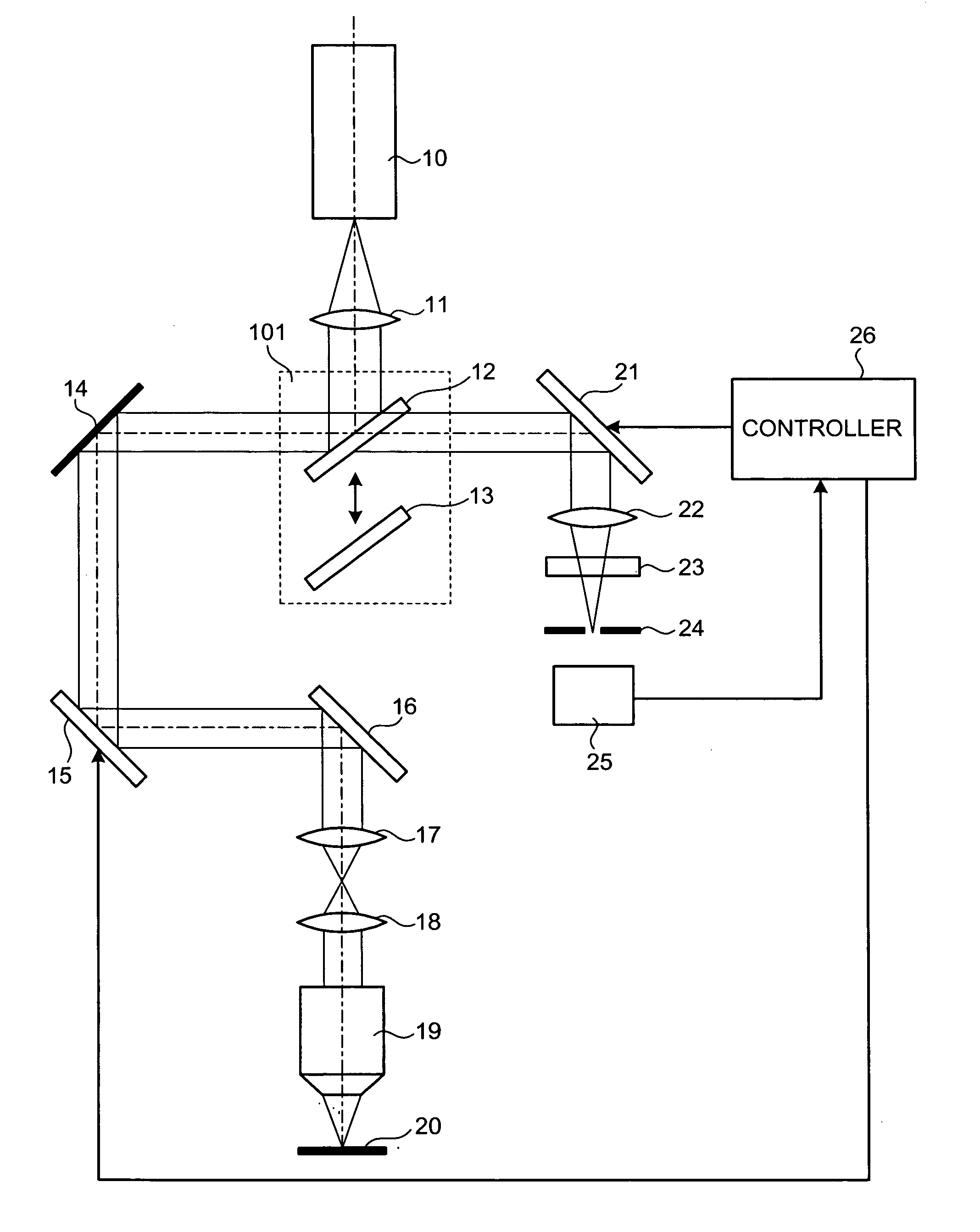
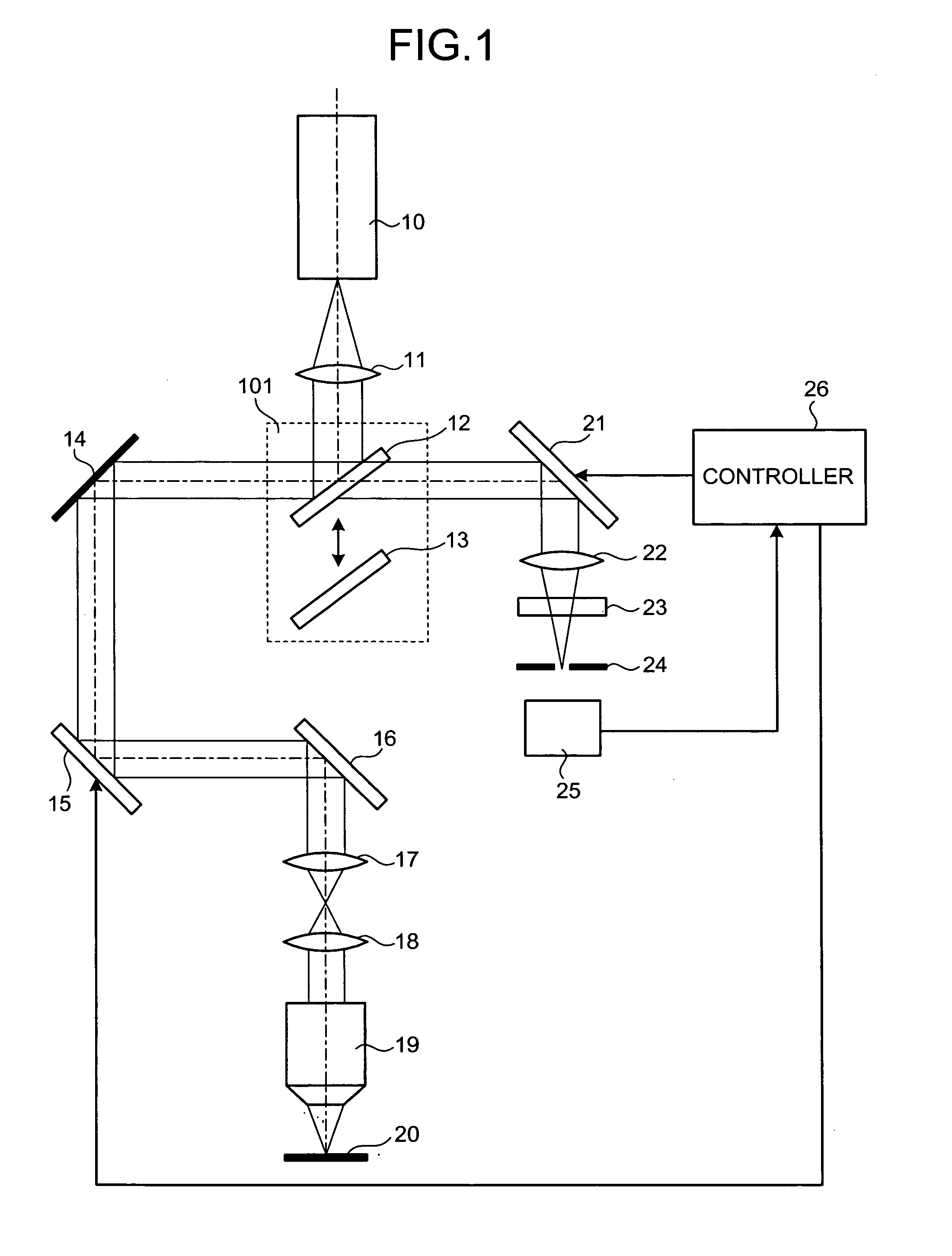
[0021]FIG. 1 is a schematic drawing showing a configuration of a laser scanning microscope according to the present invention. Referring to FIG. 1, a laser beam source, which is represented by “10”, generates a laser beam with a wavelength capable of exciting a fluorescent dye described later in a sample 20. A collimate optical system 11 is arranged on an optical path of the laser beam emitted by the laser beam source 10. The collimate optical system 11 produces a complete parallel beam from the laser beam emitted by the laser beam source 10, while changing the beam diameter.

[0022] An optical element switching unit 101, which is a light selecting unit, is arranged on an optical path of the parallel beam from the collimate optical system 11. The optical element switching unit 101 includes a half mirror 12 and a dichroic mirror 13. The half mirror 12 and the dichroic mirror 13 can be selectively switched to be arranged on the optical path. When a focusing position of an objective lens...

second embodiment

[0050] The setting of the diameter of the confocal pinhole 24 and the arrangement of the optimum absorption filter 23 on the optical path are both performed in the second embodiment; however, it is possible to prepare and perform one of the setting and the arrangement.

[0051] Further, for example, plural images of the sample in the direction of the Z-axis can be obtained at different observation positions by actively shifting the focusing position of the objective lens 19 by the first deformable mirror 15. Here, only a light that matches the focal point of the objective lens 19 can be made to pass through the confocal pinhole 24 by setting an optimum diameter of the confocal pinhole 24 in accordance with the focusing position of the objective lens 19. Consequently, the resolving power in the direction of the Z-axis is secured, and a high-quality image of the sample can be obtained.

[0052] A third embodiment of the present invention is explained hereinafter. FIG. 4 is a schematic drawi...

third embodiment

[0056] For example, in an observation of a multi-color stained fluorescent sample, two types of laser wavelengths λ1 and λ2 are selected as an exciting light, and scanning is performed by the optical scanning unit. Fluorescence is generated in response to the light beam of each exciting wavelength. The generated fluorescence is detected for image formation. When one wishes to sequentially detect different fluorescent wavelengths for each line of the raster scan by switching the laser wavelength, the line is first scanned in the X-direction only by the laser wavelength λ1 for fluorescence detection, and then the same line is scanned by the laser wavelength λ2 for fluorescence detection. Then, the scanning is shifted in the Y direction by one pixel, and a new line is scanned twice in the X-direction sequentially by the laser wavelengths λ1 and λ2. The procedure just mentioned is repeated to generate an image of one frame for each of the laser wavelengths λ1 and λ2. Here, the wavelengt...


PUM


Abstract

Provided is a laser scanning microscope having a first focusing-position control unit; and a confocal detecting unit. The first focusing-position control unit shifts a first focusing position of a laser beam on a sample in a direction of an optical axis of an objective lens. The confocal detecting unit has a confocal aperture for a confocal detection of a light emitted from the first focusing position. The microscope may include a second focusing-position control unit shifts a second focusing position of the light emitted from the first focusing position focused by the confocal detecting unit in a direction of an optical path thereof.

Description

CROSS-REFERENCE TO RELATED APPLICATIONS [0001] This application is based upon and claims the benefit of priority from Japanese Patent Application No. 2005-202004, filed Jul. 11, 2005, the entire contents of which are incorporated herein by reference. BACKGROUND OF THE INVENTION [0002] 1. Field of the Invention [0003] The present invention relates to a laser scanning microscope that can correct aberration and can change a focusing position of the objective lens. [0004] 2. Description of the Related Art [0005] Recently, a laser scanning microscope that can acquire an image with higher quality is demanded; therefore, a laser scanning microscope that can correct aberration remained in an optical element (e.g., objective lens) focusing a light emitted from a light source on a sample has been used. [0006] A microscope disclosed in JP-A No. H11-101942 (KOKAI) (U.S. Pat. No. 6,771,417) is known as an optical microscope that can correct the aberration of the objective lens. Specifically, in ...

Claims


Application Information

Patent Timeline
IPC IPC(8): G02B27/40G02B27/64
CPCG02B21/0064G02B21/006
Inventor RI, SEI
Owner EVIDENT CORP
Why Eureka
Try Eureka