Phase change memory with adjustable resistance ratio and fabricating method thereof

a phase change memory and resistance ratio technology, applied in the field of phase change memory, can solve the problems of excessive r-ratio, difficulty in circuit design, and not being useful to circuit designers, and achieve the effects of convenient circuit design, reduced write current, and easy to meet operation conditions

Inactive Publication Date: 2007-01-11
IND TECH RES INST
View PDF5 Cites 75 Cited by
  • Summary
  • Abstract
  • Description
  • Claims
  • Application Information

AI Technical Summary

Benefits of technology

[0014] The structure disclosed according to the embodiment is very convenient for circuit design under the condition that the R-ratio is adjustable, and is easy to meet the operation condition of the complementary metal-oxide semiconductor (CMOS) in the linear region. Also, the write current can be reduced by the material selection and structure thickness adjustment to improve the performance of the memory property, the process of which is very simple and can reducing the contact area, thus saving the operating power.
[0015] The structure disclosed according to the embodiment provides a preferable method to adjust the R-ratios between two states of phase change memory. With an interfacial layer, current can reach the upper electrode via a new path formed by the interfacial layer through passing by the amorphous region the phase change material is formed with the amorphous region. The resistance provided by this new path is a new high resistance (R-high), while the amorphous region only used as a switch of the path. Therefore, the R-ratio can be adjusted by the selection of the material of the interfacial layer and the coating thickness, and under the condition that the R-ratio is adjustable, the convenience of the circuit design can thus be increased. Furthermore, the selection of the material and the structure thickness adjustment can also be used to reduce the write current, so as to reduce the operating power of the memory.

Problems solved by technology

Therefore, the amorphous area formed according to the design will cover the lower electrode completely, resulting in a excessively high R-ratio, and higher voltage is required to provide enough current, which will cause the difficulties in circuit design.
On the part of current techniques for developing the phase change memory, the value of R-ratio is either thousands of times as large, or only 2˜3 times, which is not a useful property for the circuit designers.
However, the structure and method of the phase change memory disclosed in current techniques haven't proposed efficient solutions for adjusting the R-ratio of the phase change memory.

Method used


Image

  • Phase change memory with adjustable resistance ratio and fabricating method thereof
  • Phase change memory with adjustable resistance ratio and fabricating method thereof
  • Phase change memory with adjustable resistance ratio and fabricating method thereof

Examples


Embodiment Construction

[0027] The present invention will be described in details in combination with the embodiments in order for further understanding to the objects, structures, features and functions of the present invention.

[0028] Reference in the specification to “one embodiment” or “an embodiment” means that a particular feature, structure, or characteristic described in connection with the embodiment is included in at least one embodiment of the invention. The appearances of the phrase “in one embodiment” in various places in the specification are not necessarily all referring to the same embodiment.

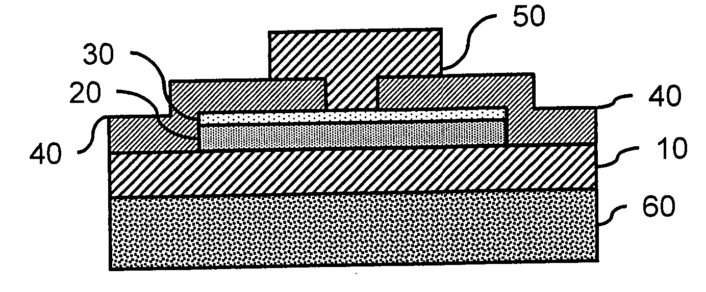
[0029] Referring to FIG. 1, which is a phase change memory with adjustable resistance ratio disclosed in the present invention. The phase change memory in this embodiment is composed of a first electrode 10, a phase change layer 20, an interfacial layer 30, a dielectric layer 40 and a second electrode 50.

[0030] The phase change layer 20 is formed on the first electrode 10, wherein a first contact are...


PUM


Abstract

A phase change memory with adjustable resistance ratio is disclosed, which includes a phase change layer and an interfacial layer formed to be in contact with each other, and at least two electrodes in contact with the phase change layer and the interfacial layer respectively. The contact sections between the two electrodes and the phase change layer and the interfacial layer define a contact area respectively, wherein, the area defined by the contact section between the electrode and the phase change layer is larger than the area defined by the contact section between the electrode and the interfacial layer.

Description

[0001] This Non-provisional application claims priority under 35 U.S.C. §119(a) on Patent Application No(s). 094123290 filed in Taiwan, R.O.C. on Jul. 8, 2005, the entire contents of which are hereby incorporated by reference. BACKGROUND OF THE INVENTION [0002] 1. Field of Invention [0003] The present invention relates to a phase change memory, and particularly to a phase change memory having a functional layer with adjustable resistance ratio. [0004] 2. Related Art [0005] Common electronic products usually require combination of various memories, among which the DRAM, SRAM, Flash and the like are the most popular. Recently, several new memory techniques including the FeRAM, MRAM and Phase Change Memory are being developed. [0006] A phase change memory can meet the requirements for rapid mass storage and long term data storage. It does not only have a small volume, and can store more data rapidly, but also can be preserved at 130 for more than ten years. The phase change memory has ...

Claims


Application Information

Patent Timeline
Patent Type & Authority Applications(United States)
IPC IPC(8): H01L31/058H01L29/06H01L29/02H01L47/00G11C11/00
CPCH01L45/06H01L45/1233H01L45/1675H01L45/144H01L45/128H01L45/126H10N70/861H10N70/8413H10N70/231H10N70/8828H10N70/063H10N70/826
Inventor WANG, WEN-HANLIANG, JIUH-MINGYEH, JYI-TYANCHIOU, SHAN-HAW
Owner IND TECH RES INST
Why Eureka
Try Eureka