Apparatus and method capable of a high fundamental acoustic resonance frequency and a wide resonance-free frequency range

a fundamental acoustic resonance and frequency technology, applied in piezoelectric/electrostrictive/magnetostrictive devices, electrical apparatuses, electrical equipment, etc., can solve the problems of limited capacitance range, low power handling capability, low q, etc., and achieve the effect of reducing the amplitude of resonan

Inactive Publication Date: 2007-01-11
NXP USA INC
View PDF33 Cites 17 Cited by
  • Summary
  • Abstract
  • Description
  • Claims
  • Application Information

AI Technical Summary

Benefits of technology

[0006] An embodiment of the present invention provides an apparatus capable of a high fundamental acoustic resonance frequency, comprising a substrate, a bottom electrode layer adjacent the substrate, a voltage tunable dielectric layer adjacent the bottom electrode layer, the voltage tunable dielectric layer including an active region, a top electrode adjacent the voltage tunable dielectric layer, a final interconnect layer connected to the top electrode via an interlayer, and wherein the top and bottom electrodes are at a predetermined thickness such that a desired high fundamental acoustic resonance is obtained. The active region of the voltage tunable dielectric layer may be approximately the length of the top electrode and the interlayer and the final interconnect layer may cover only a small fraction of the active region of the voltage tunable dielectric layer, thereby reducing the amplitude of resonances due to the interlayer or final interconnect layer.

Problems solved by technology

The most commonly used varactor is semiconductor diode varactor, which has the advantages of high tunability and low tuning voltage, but suffers low Q, low power handling capability, and limited capacitance range.
However, the aforementioned thin BST layers are impractical due to manufacturability and linearity considerations.

Method used


Image

  • Apparatus and method capable of a high fundamental acoustic resonance frequency and a wide resonance-free frequency range
  • Apparatus and method capable of a high fundamental acoustic resonance frequency and a wide resonance-free frequency range
  • Apparatus and method capable of a high fundamental acoustic resonance frequency and a wide resonance-free frequency range

Examples


Embodiment Construction

[0016] In the following detailed description, numerous specific details are set forth in order to provide a thorough understanding of the invention. However, it will be understood by those skilled in the art that the present invention may be practiced without these specific details. In other instances, well-known methods, procedures, components and circuits have not been described in detail so as not to obscure the present invention.

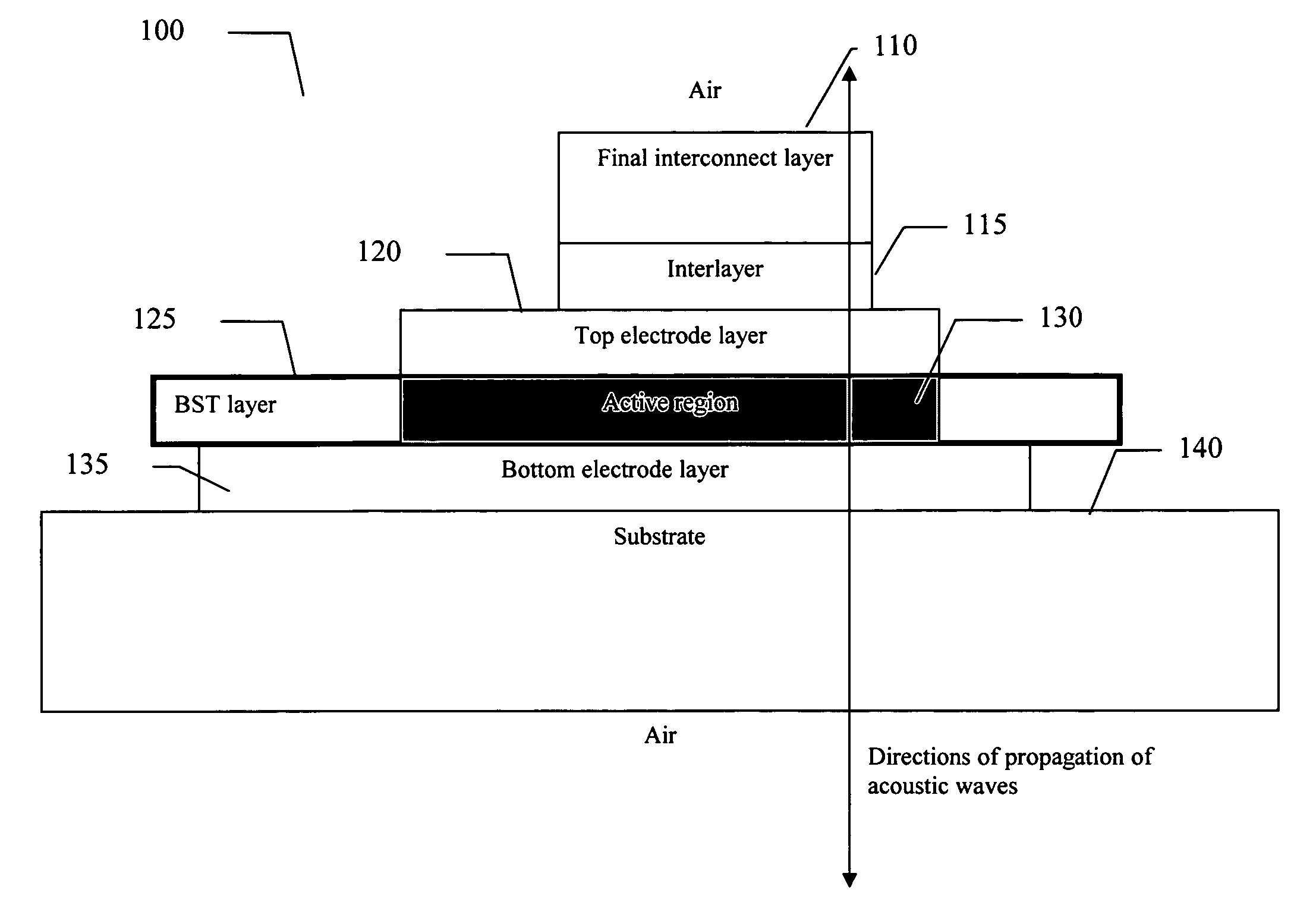
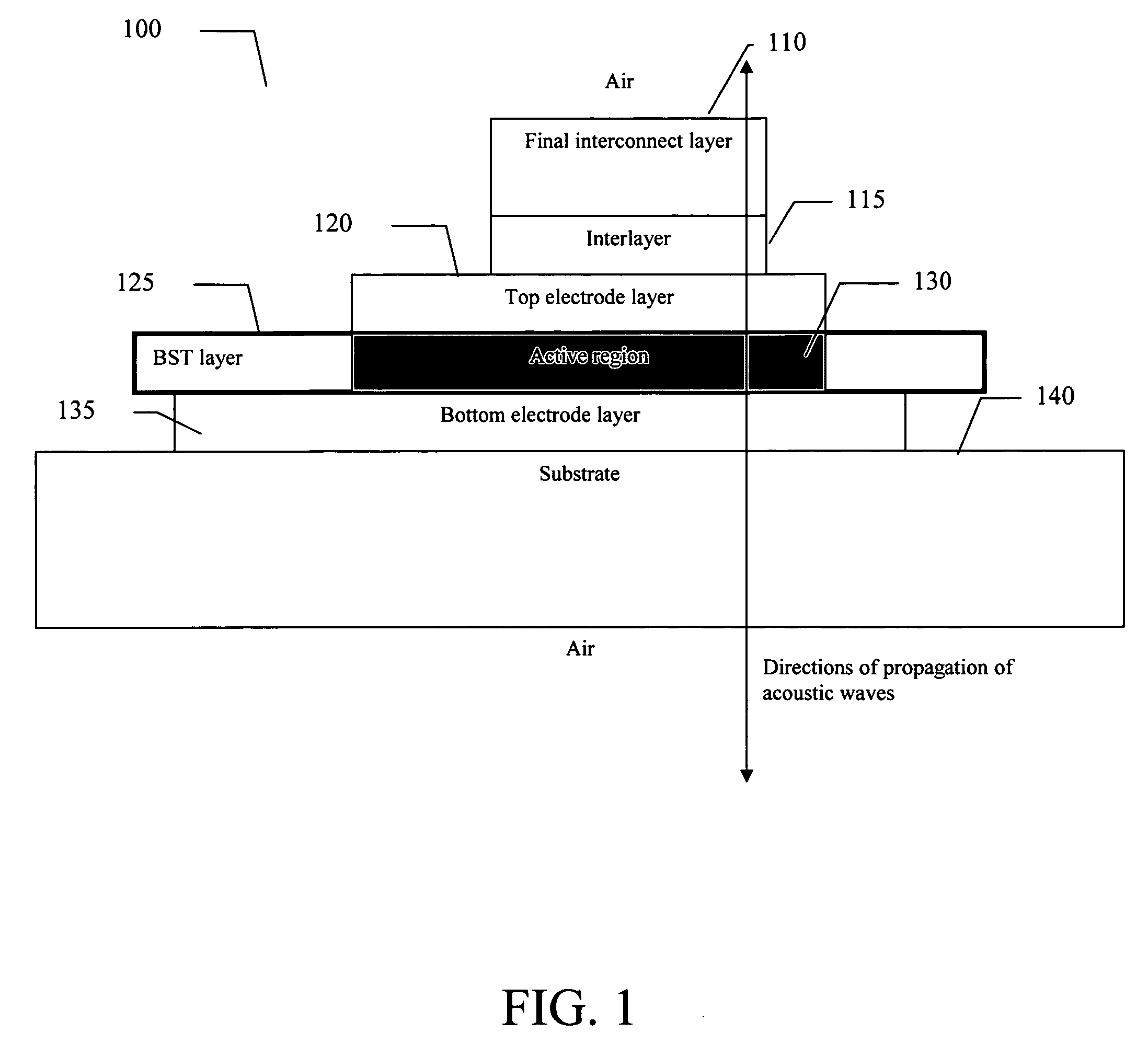
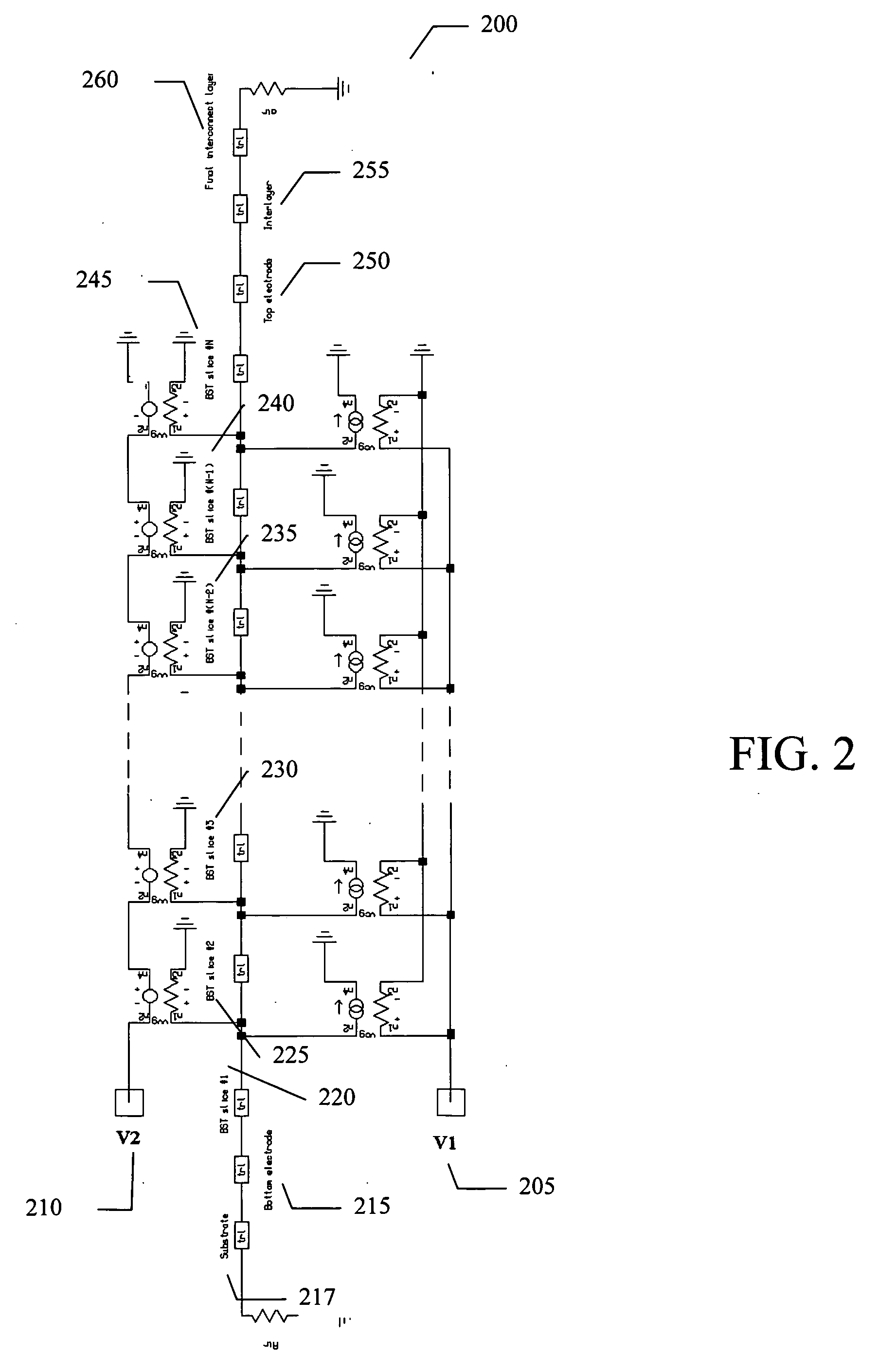
[0017] An embodiment of the present invention provides a method of modeling the electrostrictive effect and acoustic resonances that facilitates the design of arbitrary circuits in the acoustic domain of the PTC structure. Provided herein is a first exemplary acoustic circuit design involving BST layers of practical thickness with metal layers arranged such that a sufficiently high fundamental frequency of the acoustic resonance can be achieved. It is understood that this circuit is merely illustrative and the present invention is not limited to any par...


PUM


Abstract

An embodiment of the present invention provides an apparatus capable of a high fundamental acoustic resonance frequency, comprising a substrate, a bottom electrode layer adjacent the substrate, a voltage tunable dielectric layer adjacent the bottom electrode layer, the voltage tunable dielectric layer including an active region, a top electrode adjacent the voltage tunable dielectric layer, a final interconnect layer connected to the top electrode via an interlayer, and wherein the top and bottom electrodes are at a predetermined thickness such that a desired high fundamental acoustic resonance is obtained. The active region of the voltage tunable dielectric layer may be approximately the length of the top electrode and the interlayer and the final interconnect layer may cover only a small fraction of the active region of the voltage tunable dielectric layer, thereby reducing the amplitude of resonances due to the interlayer or final interconnect layer.

Description

BACKGROUND OF THE INVENTION [0001] Varactors are voltage tunable capacitors in which the capacitance is dependent on a voltage applied thereto. Although not limited in this respect, this property has applications in electrically tuning radio frequency (RF) circuits, such as filters, phase shifters, and so on. The most commonly used varactor is semiconductor diode varactor, which has the advantages of high tunability and low tuning voltage, but suffers low Q, low power handling capability, and limited capacitance range. A new type of varactor is a ferroelectric varactor in which the capacitance is tuned by varying the dielectric constant of a ferroelectric material by changing the bias voltage. Ferroelectric varactors have high Q, high power handling capacity, and high capacitance range. [0002] One ferroelectric varactor is disclosed in U.S. Pat. No. 5,640,042 entitled “Thin Film Ferroelectric Varactor” by Thomas E. Koscica et al. That patent discloses a planar ferroelectric varactor...

Claims


Application Information

Patent Timeline
Patent Type & Authority Applications(United States)
IPC IPC(8): H01L41/00
CPCH03H9/176H01G7/06
Inventor TOIT, NICOLAAS DUSENGUPTA, LOUISE C.
Owner NXP USA INC
Why Eureka
Try Eureka