Correction table creation method for head position control, head position control method and disk device

a correction table and head position technology, applied in the direction of recording information storage, maintaining head carrier alignment, instruments, etc., can solve the problems of deteriorating positioning accuracy, difficult measurement and correction, and inability to accurately record servo signals during stw, so as to achieve the effect of reducing the rro after correction

Active Publication Date: 2007-01-11
KK TOSHIBA
View PDF1 Cites 5 Cited by
  • Summary
  • Abstract
  • Description
  • Claims
  • Application Information

AI Technical Summary

Benefits of technology

[0045] It is another object of the present invention to provide a method of optimizing the gain when one of the correction values, Rro or URro, is added to the correction table, so as to create a correction table that satisfies the specifications of the positioning accuracy in a short time, and a head positioning control method and a disk device thereof.
[0046] It is still another object of the present invention to provide a correction table creation method of setting the gain, when one of the correction values Rro or URro is added to the correction table, at an optimum level for each frequency, so as to effectively suppress RPE after correction, and a head positioning control method and a disk device thereof.
[0055] According to the present invention, an adjusted gain based on the ratio of the magnitude between the components synchronizing rotation of the disk and the components not synchronizing rotation of the disk in the position signals is used, so the gain to minimize RRO after correction can be theoretically determined using an expression for determining RRO after correction. Therefore the gain can be determined without depending on experiment. Also the value of RRO after correction can be guaranteed, and the manufacturing time and device specifications can be determined.

Problems solved by technology

But the position signals include noise, which deteriorates the positioning accuracy.
For the component not synchronizing with rotation, on the other hand, measurement and correction are difficult.
The first cause is that the servo signals are not accurately recorded concentrically during STW.
As long as the servo signals are mechanically recorded, mechanical, electrical and magnetic noises during recording are unavoidable.
Therefore accurately recording the servo signals concentrically during STW is extremely difficult.
The second cause is that distortion occurs to the disk and spindle motor after STW.
The track width of current disk devices is around 200 nano meter, so the influence even of a slight distortion on positioning accuracy is extremely large.
If RRO occurs, the positioning accuracy of the head deteriorates, which causes problems in recording and regenerating data.
This means that even if RRO can be suppressed, the same suppression rate cannot always be implemented for RPE.
A problem of generating the waveform of RroTable and URroTable is noise, particularly the asynchronous component in the position disturbance: NRRO.
A waveform is determined using position signals regardless whether the actuator follows up the RRO-or not, but the problem occurs when NRPE is most obviously large compared with RPE.
A method of simply averaging can decrease the influence of NRPE, but cannot suppress it to “0”.
Therefore it is unavoidable that an optimum value must be determined by experiment based on experience.
Therefore the suppression rate of RPE after correction cannot be estimated and must be confirmed by experiment.
This is a problem when the suppression rate is adjusted for each disk device, making it impossible to estimate the positioning accuracy value when a new device is designed.
Also when the correction value is measured in the manufacturing steps of the disk device, it is difficult to set a standard for the RPE measurement time, that is the manufacturing time, required for satisfying the specifications of the positioning accuracy.
For example, according to a prior art, a more accurate RRO correction table can be created as the measurement time becomes longer (e.g. several hours), to satisfy the specifications of the positioning accuracy, but as the measurement time becomes longer, the ratio of the correction table creation time in the manufacturing steps becomes longer, which is inappropriate for manufacturing large quantities of disk devices.
Also when gain is determined by experiment, the frequency characteristic of the position error is not considered, so it is difficult to effectively suppress RPE after correction, which may drop the follow-up accuracy of the disk device.

Method used


Image

  • Correction table creation method for head position control, head position control method and disk device
  • Correction table creation method for head position control, head position control method and disk device
  • Correction table creation method for head position control, head position control method and disk device

Examples


first embodiment

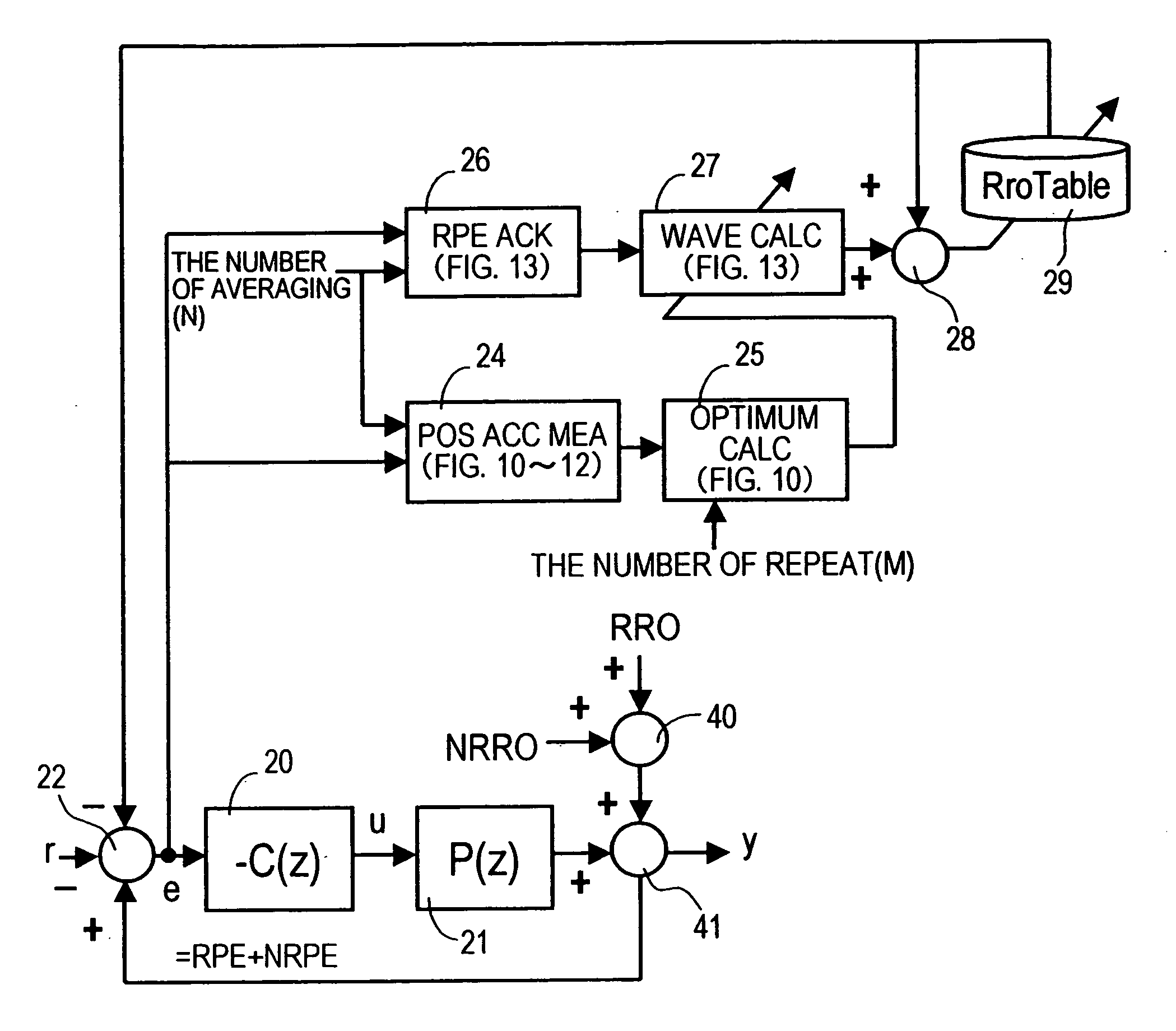
[0118]FIG. 7 is a block diagram depicting the head positioning control system of the present invention, FIG. 8 is a flow chart depicting the manufacturing steps of the disk device of the present invention, FIG. 9 is a diagram depicting the residual RRO for creating RroTable, FIG. 10 is a flow chart depicting the RRO gain optimum value calculation processing using the residual RRO in FIG. 9, FIG. 11 is a flow chart depicting the RRO measurement processing, and FIG. 12 is a flow chart depicting the NRRO measurement processing in FIG. 10.

[0119]FIG. 7 is a block diagram for the case when the optimum value calculation and the correction table creation are performed on a single disk device unit, and composing elements the same as those in FIG. 6 are denoted with the same reference numerals. In other words, the error ‘e’ between the target position ‘r’ and the current (observing) position ‘y’ is determined by the computation block 22, the controller 20 performs control computation, calcula...

second embodiment

[0181]FIG. 19 is a block diagram depicting the RRO correction table creation system according to the present invention. In FIG. 19, composing elements the same as FIG. 7 are denoted with the same reference numerals, and the difference from FIG. 7 is that the optimum gain calculation processing 25 (FIG. 10) is executed by an external device (e.g. personal computer) 50 connected to the disk device, and the result is set in the gain table 30 in the disk device.

[0182] If this configuration is used, the addition gain is calculated using the external device 50, so the load of the MCU 14 in the disk device can be decreased, and the addition gain can be calculated at high-speed.

third embodiment

[0183]FIG. 20 is a block diagram depicting the RRO correction table creation system according to the present invention. In FIG. 20, composing elements the same as FIG. 7 are denoted with the same reference numerals, and the difference from FIG. 7 is that the positioning accuracy measurement processing 24, the optimum gain calculation processing 25 (FIG. 10-FIG. 12), the RPE acquisition processing 26 (FIG. 13), and the waveform calculation processing 27 (FIG. 13) are executed by an external device (e.g. personal computer) 50 connected to the disk device, and the result is set in the RRO correction table 29 in the disk device.

[0184] When this configuration is used, the table values of the RRO correction table 29 are calculated, so the load of the MCU 14 of the disk-device can be decreased further, and the table values can be calculated at high-speed. Also the correction table creation processing program is unnecessary in the disk device after shipment of the disk device, so the time r...


PUM

PropertyMeasurementUnit
frequencyaaaaaaaaaa
current positionaaaaaaaaaa
voltageaaaaaaaaaa

Abstract

A head position control system control the position of the head by correcting the components synchronizing rotation of the disk from the head control amount, in which an adjusted gain to minimize the components synchronizing rotation after correction is theoretically acquired. An adjusted gain based on the ratio of the magnitude between the components synchronizing rotation of a disk and the components not synchronizing rotation of the disk in the position signals is used. And a gain to minimize RRO after correction can be theoretically determined using an expression to determine RRO after correction. The gain can be determined without depending on experiment, and the value of RRO after correction can be guaranteed, therefore the manufacturing time and the device specifications can be determined.

Description

CROSS-REFERENCE TO RELATED APPLICATIONS [0001] This application is based upon and claims the benefit of priority from the prior Japanese Patent Application No. 2004-263631, filed on Sep. 10, 2004, the entire contents of which are incorporated herein by reference. BACKGROUND OF THE INVENTION [0002] 1. Field of the Invention [0003] The present invention relates to a correction table creation method for head position control for a disk device which controls the position of a head to a rotating disk for one or both of reading and writing information from / to the disk, and head position control method and the disk device thereof, and more particularly to a correction table creation method for head position control for correcting the rotation synchronization component of the position signals, and the head position control method and disk device thereof. [0004] 2. Description of the Related Art [0005] Disk storage devices for recording to and regenerating from a rotating disk medium are wid...

Claims


Application Information

Patent Timeline
Patent Type & Authority Applications(United States)
IPC IPC(8): G11B5/596G11B21/02
CPCG11B5/59627G11B21/10
Inventor TAKAISHI, KAZUHIKO
Owner KK TOSHIBA
Why Eureka
Try Eureka