Magnetic head and method of manufacturing the same

a magnetic head and manufacturing method technology, applied in the field of thin film magnetic head, can solve problems such as accuracy errors in machining to achieve the required mr element height, and achieve the effect of high accuracy

Inactive Publication Date: 2007-01-11
HITACHI LTD
View PDF0 Cites 13 Cited by
  • Summary
  • Abstract
  • Description
  • Claims
  • Application Information

AI Technical Summary

Benefits of technology

[0016] The object of the present invention is to provide a structure of a magnetic head of which the MR element height can be machined with high accuracy and a method of manufacturing the magnetic head.
[0023] As described above, one of the two magneto-resistive effect elements arranged for each slider is used for measuring the lapping amount of the slider, and when the resistance value or the height of the magneto-resistive effect element converted from the resistance value reaches a predetermined value, the lapping process of the particular slider is completed. It is thus possible to realize a thin-film magnetic head having the height of the magneto-resistive effect elements controlled with a high accuracy.

Problems solved by technology

The technique described above has the disadvantage that an error of accuracy of machining for achieving the required MR element height is caused by the following factors:
(1) An error in forming an exposure mask used for forming the magneto-resistive effect elements and the electric lapping guide elements on a substrate and the exposure error in the exposure process thereof.
(2) An error caused by the difference in the lapping amount due to the distance between the positions of the magneto-resistive effect elements and the electric lapping guide element to be formed.
(3) An error caused by the inclination component, quadratic curve component and the swell component in the MR element height distribution in the row bar that cannot be corrected in the air-bearing surface lapping process.

Method used


Image

  • Magnetic head and method of manufacturing the same
  • Magnetic head and method of manufacturing the same
  • Magnetic head and method of manufacturing the same

Examples


Embodiment Construction

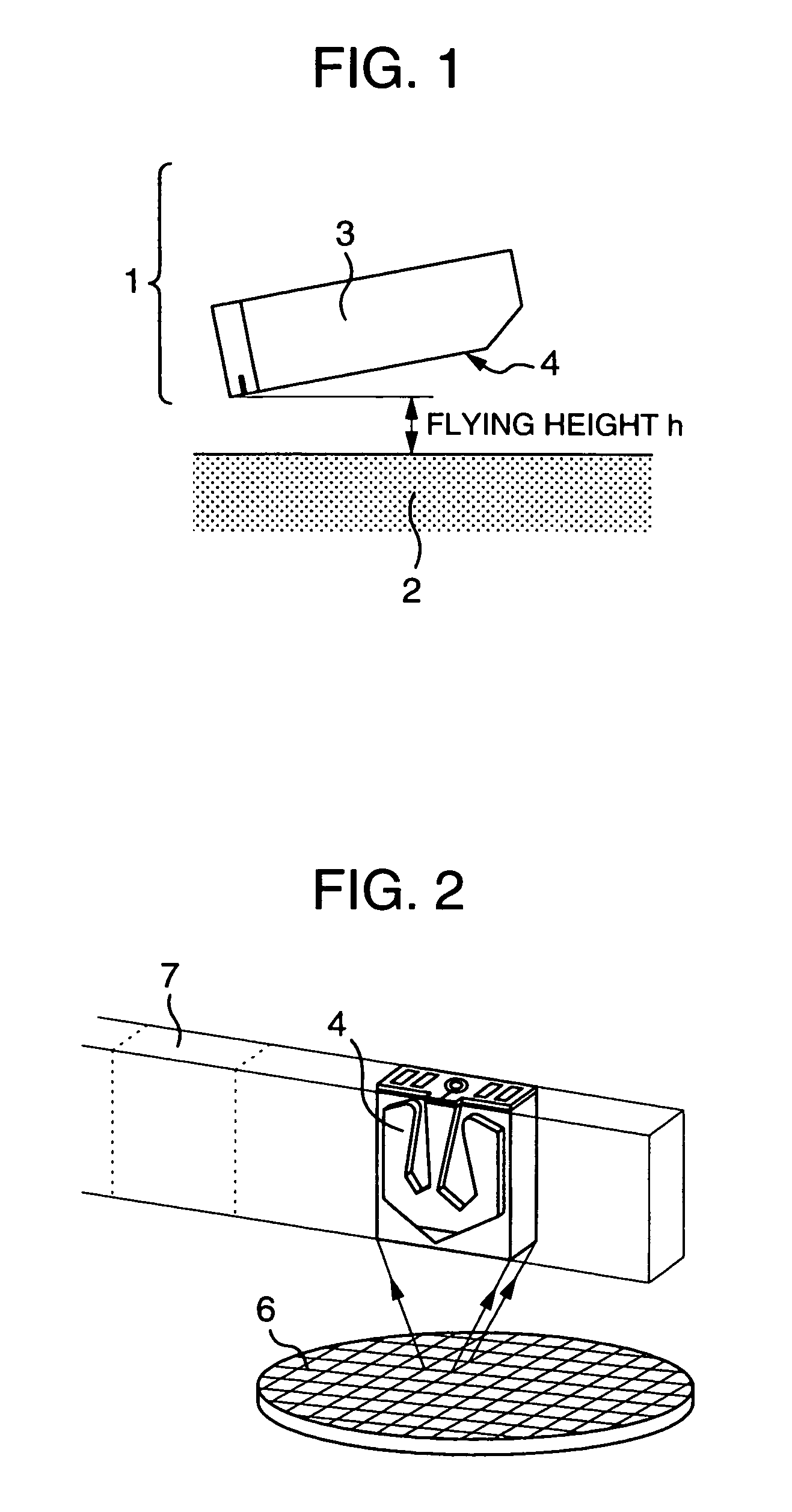
[0040] First, an outline of a magnetic disk drive will be explained. FIG. 1 is a diagram for explaining the layout of a magnetic head 1 and a disk 2. The magnetic head 1 is configured of a slider 3 and a magneto-resistive effect element 5 formed on the slider 3 and arranged in a plane perpendicular to the slider surface 4. In a magnetic disk drive of CSS (contact start stop) type, the magnetic head 1, or exactly, an end portion of the magneto-resistive effect element 5 is flown by a very small amount over the surface of the disk 2 utilizing the dynamic pressure caused by the rotation of the disk 2 making up a magnetic recording medium thereby to write (record) or read (reproduce) information into or from the disk 2. In the process, the gap between the surface of the disk 2 and the magneto-resistive effect element 5 is defined as the flying height h. The smaller the flying height h, the higher the recording or reproduction efficiency.

[0041] The magnetic head 1 will be explained with...


PUM

PropertyMeasurementUnit
heightaaaaaaaaaa
heightaaaaaaaaaa
heightaaaaaaaaaa

Abstract

A thin-film includes an inductive element and a first and second magneto-resistive effect elements in which the first and second magneto-resistive effect elements are arranged in proximity to each other on a substrate, and one surface of the substrate perpendicular to the surface formed with the first and second magneto-resistive effect elements constitutes a slider surface, thereby providing appropriate hight of the magneto-resistive effect elements.

Description

BACKGROUND OF THE INVENTION [0001] The present invention relates to a thin-film magnetic head having magneto-resistive effect elements, or in particular to a structure and a method of manufacturing a thin-film magnetic head for controlling the height of the magneto-resistive effect elements with high accuracy. [0002] In recent years, the size of the magnetic disk drive has been ever on the decrease with the capacity thereof even on the increase, and small-sized magnetic disk drives using a 3.5-inch disk and 2.5-inch disk, respectively, are now the main stream. Among the magnetic heads used for these small-sized magnetic disk drives, the magnetic induction head of which the read output depends on the rotational speed of the disk has too small a disk rotational speed to produce a sufficient read output. With a magneto-resistive effect head using a magneto-resistive effect element having a resistance value changing with the magnetic field, on the other hand, the read output is not depe...

Claims


Application Information

Patent Timeline
Patent Type & Authority Applications(United States)
IPC IPC(8): G11B5/60G11B15/64G11B5/10G11B5/187G11B5/31G11B5/39G11B5/48
CPCG11B5/102G11B5/1871G11B5/3106G11B5/3166Y10T29/49041G11B5/3173G11B5/3967G11B5/488G11B5/6005G11B5/3169
Inventor YAMAKURA, HIDEOTAMURA, TOSHIOTANAKA, KOJI
Owner HITACHI LTD
Why Eureka
Try Eureka